

About M7
Product Introduction
M7 is a half-body general-purpose humanoid robot developed by Robotera. It has 42 degrees of freedom, motors with a maximum peak torque of 184 Nm and a peak speed of 4.20 rad/s, and two dexterous hands with 12 active degrees of freedom each. It supports teleoperation, imitation learning, and robot foundation-model algorithms for logistics, data collection, and research applications.
Overview
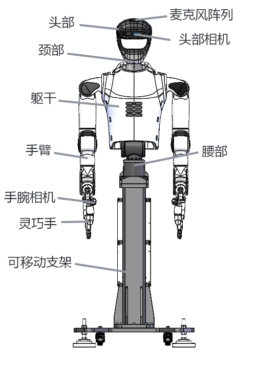
The overall appearance of the robot is shown below.
Illustrations in this manual are for reference only. Refer to the physical product delivered for your project.
Product Features
Fast Deployment and Ease of Use
- Low risk and cost, quick return, high flexibility, and easy upgrades and expansion.
- Sound and light alarms plus voice prompts support a user-friendly human–robot interface.
- Supports data-collection teleoperation and robot foundation-model applications.
- Plug-and-play operation without battery-life limitations.
High Sorting Efficiency and Space Utilization
- Supports small-item sorting at a rate of 1,000 items per hour or higher.
- Operates directly within the existing human workspace without requiring additional space.
Broad Compatibility
- Supports grasping at a variety of fixed workstations.
- Supports small-package feeding with multiple SKUs and unrestricted package types.
Product Dimensions
When planning the deployment and installation site, account for the robot's footprint and operating space. The following dimensions are for the standard version and are for reference only; the actual dimensions depend on the project configuration.
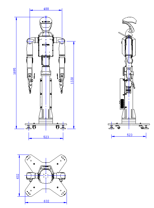
Overall Robot Parameters
Technical Specifications
| M7 Specification Parameters | |
|---|---|
| Size | Upright dimensions: Base dimensions 632*632mm, height adjustable from 1713 to 1760mm |
| Total Arm Length | 717mm x 2 |
| Single-arm load | 3 kg (rated load with dexterous hand) |
| Degree of Freedom | 42 (7 per arm × 2, 2 at the waist, 2 at the neck, and 12 per dexterous hand × 2) |
| Overall Robot Weight | Approximately 70 kg |
| End-of-arm velocity | 3m/s |
| Arm End Accuracy | 0.02mm |
| Control and perception capabilities | Determined by the onboard control and inference units delivered for the project |
| Perception Sensor Configuration | Depth Camera Voice Module |
| Dexterous Hand | It has a human hand-like shape with 12 active degrees of freedom in a single hand |
| Communication Interface | Ethernet、USB 4.0、Wi-Fi 6、USB-C |
Joints and Motors
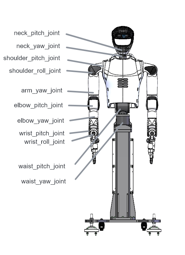
Joint Peak Torque and Speed Specifications:
| position | Peak torque (Nm) | speed (rad/s) |
|---|---|---|
| shoulder pitch | 95 | 4 |
| shoulder roll | ||
| arm yaw | ||
| elbow pitch | ||
| elbow yaw | 35 | 4 |
| wrist roll | ||
| wrist pitch | ||
| neck pitch | 35 | 4 |
| neck yaw | ||
| waist pitch | 184 | 4 |
| waist yaw |
Range of robot for each joint:
| Robot Parts | Corresponding joint angle range |
|---|---|
| Arm | Shoulder pitch: ±160°; shoulder roll: -32°~145°; shoulder yaw: -250°~70°; elbow: -135°~40°; wrist yaw: ±160°; wrist pitch: ±45°; wrist roll: ±90° |
| Neck | Neck pitch: -10°~30°; neck yaw: -60°~60° |
| Waist | Waist pitch: -10°~90°; waist yaw: -145°~145° |
Onboard Computing Resource Connection Diagram
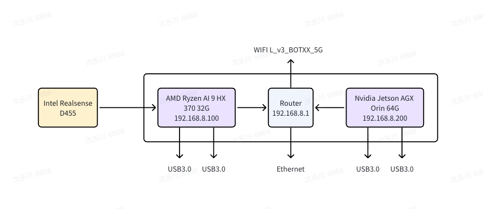 The hardware and system specifications of the onboard computing resources are listed below:
| Computing Unit Name: | AMD Ryzen AI 9 HX 470 |
|---|---|
| CPU | 12-core |
| Memory | 32GB |
| Storage | 1TB SSD |
Inference unit specifications:
| Inference Unit | i9-14900HX, 32 GB memory, 1 TB PCIe 4.0 storage, RTX 5070 Ti 16 GB |
|---|
Component Overview
Robot Composition
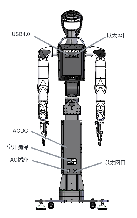
The fixed M7 humanoid robot consists of the head and neck, torso, arms, dexterous hands, waist, fixed stand, and base.
Head and Neck
- The head and neck include a 2-DoF neck and the head. The head integrates a microphone array, depth camera, light strip, and other sensors and hardware, and connects to the torso through a modular interface.
- The neck has yaw and pitch degrees of freedom, with ranges of ±60° and +30° to -10°, respectively.
- The microphone array supports voice interaction, sound-source localization, and foundation-model dialogue.
- The depth camera is mounted on the forehead and angled downward to cover the tabletop work area together with the neck pitch joint.
- The light strip can display necessary robot information through the electronic control system.
Torso
- The torso provides electromechanical mounting interfaces for the head, neck, and limbs, as well as robot interaction interfaces. It contains the main control, power, and communication hardware.
- Active airflow and passive structural cooling help reduce the risk of hardware overheating.
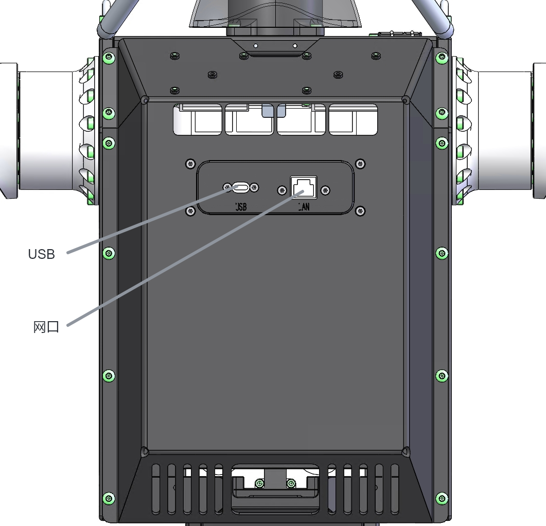
External Interfaces and Controls
| No. | Interface | Electrical specification | Function |
|---|---|---|---|
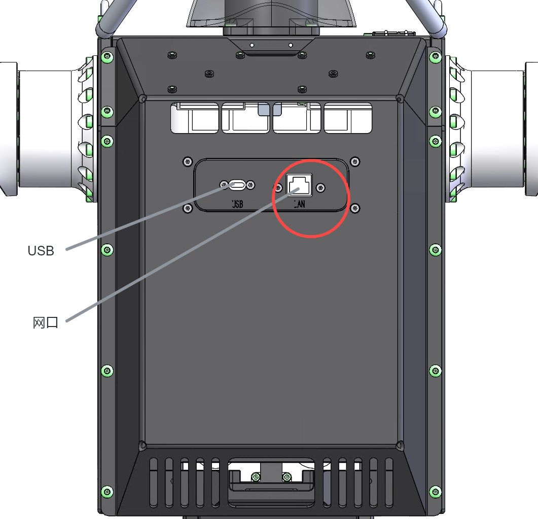
| 1 | Ethernet | Gigabit industrial Ethernet | Connects to the M7 robot |
| 2 | USB | USB 4.0 | Connects external USB devices |
Arms
- Each arm has 7 degrees of freedom with a P-R-Y-P-Y-P-R joint layout. The ranges are ±160°, outward 145°/inward 30°, outward 70°/inward 250°, forward 135°/backward 40°, ±160°, ±45°, and ±90°, respectively, with no coupling or interference between ranges.
- The rated load of one arm with a dexterous hand is no more than 3 kg. An arm without a dexterous hand has 7 degrees of freedom.
- The wrist includes a standard USB 2.0 monocular camera, a wrist EtherCAT interface, and external cable routing.
- In addition to the XHand dexterous hand, the wrist end can use an adapter to support specified electric grippers.
Dexterous Hands
| Item | Specification | Item | Specification |
|---|---|---|---|
| Weight | 1100 g | Fingertip gripping force | 15 N |
| Dimensions (L × W × H) | 191 mm × 94 mm × 47 mm | Load | 5 kg (per finger) |
| Active DoF | 12 | Furthest thumb opposition | Little finger |
| Passive DoF | 0 | Repeated opening/closing speed | >2 Hz |
| DoF distribution | Thumb ×3, index ×3, middle ×2, ring ×2, little ×2 | Backdriving damping | ≤0.1 Nm |
| Thumb transmission | 3 self-developed geared force-control joint modules | Four-finger transmission | 9 self-developed geared force-control joint modules |
| Fingertip shape | Rounded | Side-swing range | -15° to +15° (index finger) |
| Fingertip repeatability | ±0.20 mm | Communication interface | EtherCAT, RS485 (USB) |
| Control modes | Position control, current-loop force control, force-position control | Communication rate | EtherCAT: 100 MHz; RS485: 3 MHz |
Waist
- The waist uses H9015 modules with pitch and yaw degrees of freedom arranged in series.
- Pitch range: 90° forward and 10° backward. Yaw range: 145° to either side.
- The waist has a power-off brake that automatically engages during emergency stop or power loss.
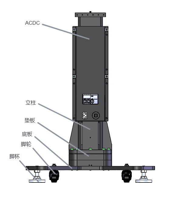
Stand
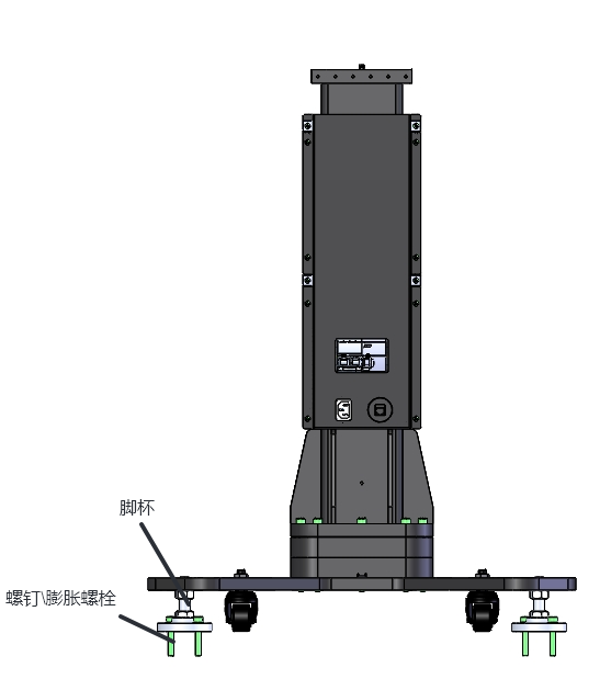
The stand supports the robot and adjusts its height. Its feet can be used for fixation and leveling, casters facilitate onsite transport, and shims adjust the stand height for different work-platform heights. The power supply converts AC to DC for the product.
Product Functions
Visual Recognition
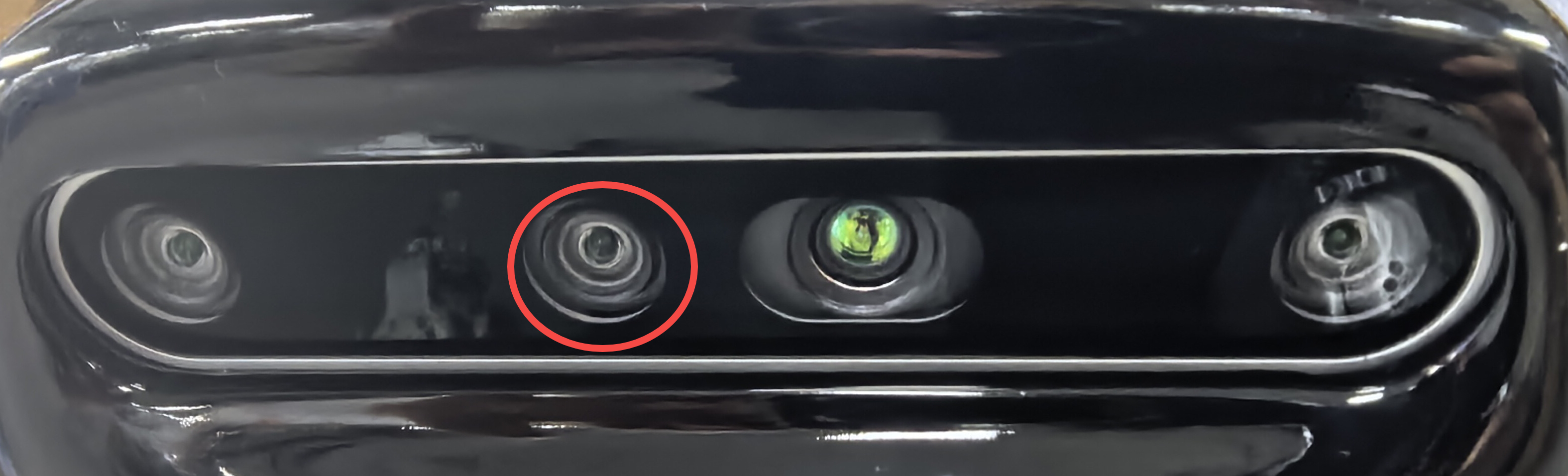
- A 3D stereo camera in the head provides an ultra-wide field of view for environment localization and global package recognition.
- A monocular camera at the wrist provides precise grasp-point localization.
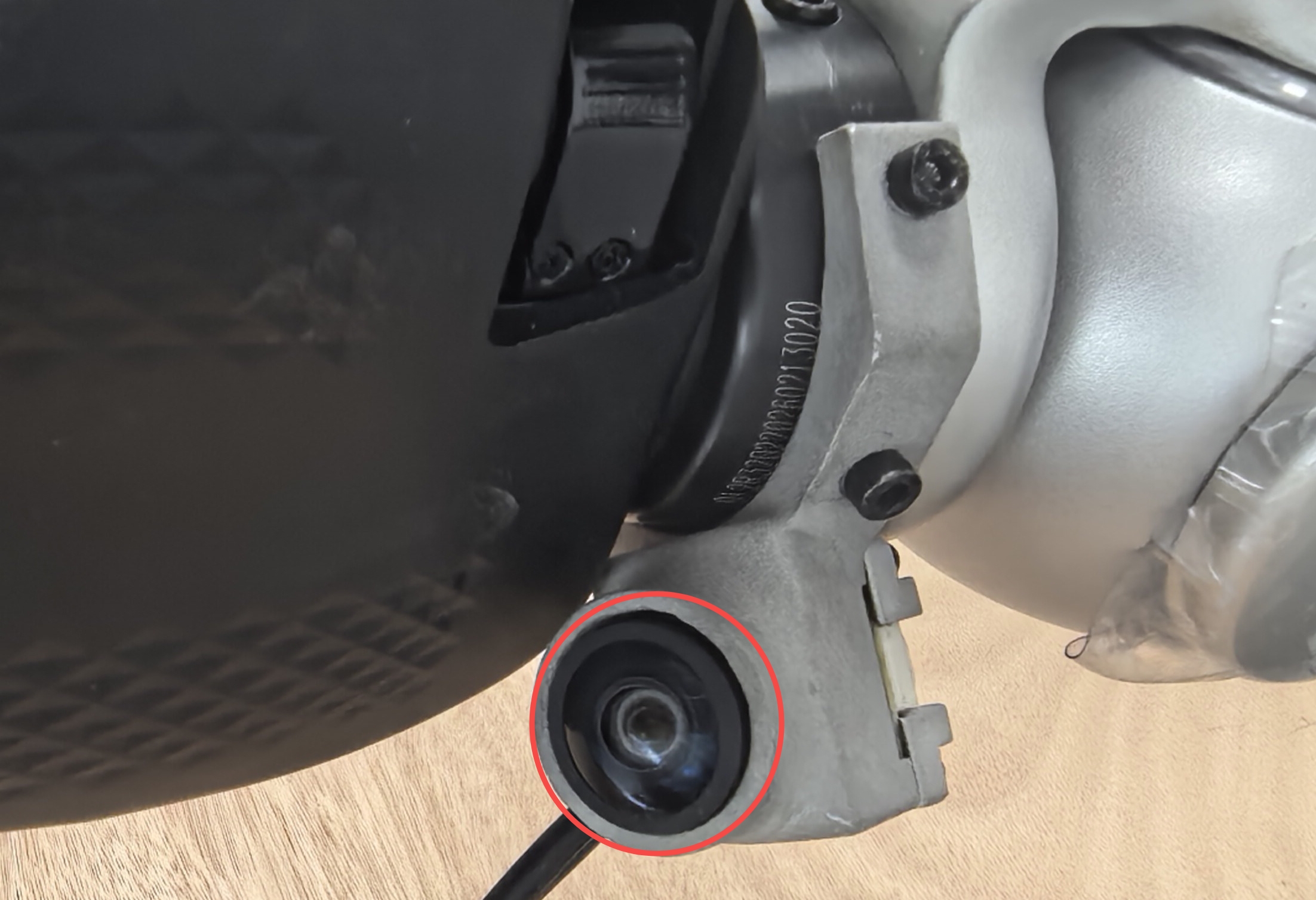
- Multi-camera visual perception provides long-range, wide-coverage, and precise grasping capability.
Arm Grasping
- One arm with a dexterous hand has a rated load of 3 kg and a maximum load of 5 kg, enabling compliant grasping of small packages and objects.
- Under load, the body tilt angle does not exceed 3°, preventing tip-over risk.
- Custom stand heights are supported.
Voice Interaction
The built-in microphone array and high-fidelity speaker support two-way audio communication, onsite voice prompts, fault voice alarms, and voice warnings for safety zones.
Network Communication
- Supports wired network communication with the inference unit for model inference.
- Supports wired network communication with scheduling and business systems.
Sound and Light Alerts
- The robot head provides status lights and visual fault alarms.
The battery-level light indications are as follows (the brightness of the white segments must be adjusted):
| Battery Level | Light Color | Flash Pattern | Battery Display Logic and Brightness | Indication |
|---|---|---|---|---|
| 100% while charging | Green | Steady | The battery is fully charged. | |
| 30%–100% | Blue/white | Steady | 1. The remaining-charge segments are blue. 2. The consumed-charge segments are white. | 1. The robot can be used normally while the battery level is above 30%. 2. The ten light segments dim progressively to indicate battery consumption. |
| 20%–30% | Yellow/white | Steady | 1. The remaining-charge segments are yellow. 2. The consumed-charge segments are white. | 1. Below 30%, the lights change to yellow to remind the user to recharge the robot. 2. The ten light segments dim progressively to indicate battery consumption. |
| 10%–20% | Orange-red/white | Steady | 1. The remaining-charge segments are orange-red. 2. The consumed-charge segments are white. | 1. Below 20%, continued use may exceed the battery's ability to supply normal operating power, and the lights change to orange-red as a warning. 2. The ten light segments dim progressively to indicate battery consumption. |
| 0–10% | Red | Remaining segments flash; consumed segments remain steady | 1. The remaining-charge segments are red. 2. The consumed-charge segments are white. | Below 10%, the robot may lose power at any time and could be damaged. The remaining-charge segments flash red as an alarm. |
- The robot head provides voice alarms so users can monitor the robot's operating state from alarm messages in real time.
Safety Protection
Emergency Stop Protection
Emergency stop is the robot's highest-priority safety function. It uses hardwired priority and software redundancy, independent of control logic, component crashes, or communication interruption. When triggered, it immediately cuts motion power, stops all movement, and locks the waist brake to prevent collision and tip-over incidents.
Runaway Prevention
Runaway prevention is a core safety function of the robot control system. It monitors robot motion in real time and triggers an emergency-stop response when it detects risks such as uncontrolled speed or abnormal commands.
Waist Brake
The waist bears the upper body's load and torsional moment. It automatically locks during power loss, emergency stop, or system failure to prevent tip-over, falling parts, or unintended movement.
Intelligent Management
Robot Support
- Supports model-command, remote-controller, and teleoperation control modes.
- Provides ROS 2.0 driver packages and an SDK.
- Supports access to joint PID parameters.
System Collaboration and Extension
- Supports tasks assigned by WCS.
- Supports autonomous tasks, local manual override, remote teleoperation, and physical-button control. Priority is emergency braking > manual control > autonomous control.
- Supports remote OTA upgrades and secondary integration through an SDK package.
Safety Information
Before using this product, carefully read and follow the precautions below to avoid hazardous situations and ensure optimal product performance.
Notice
The safety precautions in this manual supplement applicable safety rules. Operators and maintenance personnel must also comply with applicable local and international laws, regulations, and standards.
Warning Labels
| Label | Description | Location |
|---|---|---|
 | Warning label: risk of electric shock | Center of the outward-facing side of the power adapter |
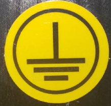 | Grounding label, 15 mm diameter | Above the hole between the reinforcing ribs at the bottom of the stand |
General Safety
General precautions:
- Before using the robot, carefully read the user manual and understand the robot's functions, operating methods, and safety precautions.
- Use the robot on a level surface. Avoid excessively high or low temperatures, humid environments, steep slopes, floors with large level differences, fragile surfaces, and areas subject to vibration.
- Provide sufficient operating space for the robot. Avoid working in narrow or crowded environments to reduce collision and crushing risks.
- Before operation, ensure that all cables, plugs, and sockets are intact. Immediately disconnect the power supply in the event of an abnormal condition such as a short circuit or overheating.
- Before starting the robot, ensure that no personnel or other obstacles are in its work area, especially near moving parts.
- Before starting the robot, verify that the system is operating normally and has completed its self-check.
Operating precautions:
- Use all robot components and accessories correctly. Unauthorized modification or disassembly is prohibited.
- Keep fingers, hair, and clothing away from robot joints, gaps, and moving parts to prevent pinching or entanglement.
- Do not touch motor surfaces during operation to prevent burns.
- Do not insert foreign objects into robot gaps; doing so may cause electric shock or a short circuit.
- Do not cover sensor areas on the torso, head, or other parts, as this may interfere with perception and control.
- Do not use the robot in harsh environments involving humidity, high temperature, or strong magnetic fields. The normal operating temperature is 0–30°C, with relative humidity below 75%.
- Do not move or transport the robot while it is powered on or before the battery has entered sleep mode.
- While the robot is executing motions, personnel must keep their distance and remain outside the motion range of the arms and legs to prevent collision injuries.
- Use dedicated relocation equipment when moving the robot. A single person must not carry or drag it manually.
- If the robot moves out of control or another abnormal condition occurs, immediately press C on the remote controller to stiff-stop all robot joints, then take protective measures as soon as possible.
- If remote-stop operations do not take effect promptly, immediately press the emergency-stop button on the robot's back to cut power and ensure safety.
- Do not disassemble the robot yourself. Contact Robotera after-sales personnel if repair is required.
Cleaning precautions:
- Keep the robot surface clean and regularly remove dust, oil, and other contaminants.
- Before cleaning the robot, disconnect the power supply and use a dry or slightly damp cloth to clean the equipment.
Transport Safety
To ensure safe transport, observe the following requirements:
- Before transport, ensure that both the robot power switch and the battery switch are off.
- During transport, the robot must not hold any object, and all mechanisms must be locked and kept stationary.
- Avoid excessive vibration and impact during transport, as these may affect robot performance.
Maintenance Safety
Before performing robot maintenance, observe the following safety requirements:
- Before maintenance, pause the robot or switch it to offline mode in the management system.
- Before maintenance, turn off the robot's power supply.
- Do not use materials that may scratch surfaces, such as metal brushes or steel wool, to clean the equipment or charging-station surface.
- Establish a safety isolation zone when troubleshooting within the robot's operating area.
- For technical support, contact Robotera using the information provided in this manual. Unauthorized technical service may invalidate the warranty.
- Notify Robotera personnel before replacing any part. Replacement may proceed only after written approval from Robotera. Robotera accepts no liability for losses or equipment downtime caused by unauthorized replacement.
- If an equipment component or power supply is defective or damaged during use, do not attempt to repair it yourself. Consult technical personnel authorized by Robotera.
Environmental Requirements
The robot has the following environmental requirements:
- The environment must be free of excessive dust, oil fumes, flammable or explosive substances, and corrosive gases.
- The floor must meet the relevant deployment requirements. Refer to the deployment-environment requirements in the technical specifications table for details.
- Avoid complex environmental interference from electromagnetic waves, scattered light, ultrasound, and similar sources wherever possible.
- Ambient illumination must be below 10,000 lx for artificial light and below 6,000 lx for daylight, with no direct sunlight.
Personnel Requirements
- This product may be used only by persons aged 18 or older and only in accordance with this manual.
- Maintain a safe distance of at least 50 cm from the robot's working range to avoid accidental collisions. Do not stand near the motion path, especially when the robot is executing high-speed motions.
- Do not directly intervene in robot motions during operation. Any adjustment or manual intervention must be performed only after the robot has stopped completely and has been powered off.
- Personnel responsible for installing, operating, or maintaining Robotera products must first receive rigorous training, understand all safety precautions, and master the correct operating and maintenance procedures to prevent accidents caused by improper operation.
- Only personnel trained by Robotera or a Robotera-authorized organization, or personnel with equivalent professional skills, may install or maintain the equipment.
- Personnel involved in installation and commissioning, operation and maintenance, programming, or system-solution development must carefully read this manual before work and use the product in strict accordance with the safety requirements.
Installation and Delivery
Unpacking Inspection
- Before opening the package, check for damage and confirm that the product was not damaged in transit.
- Remove the robot and accessories, including the power supply and tools, one by one according to the instructions.
- Follow the video guidance to remove the robot from the shipping case.
Transport
- Use the custom flight case designed for the robot and its accessories.
- Before moving the robot, fully power it off and confirm that the emergency-stop state has been released.
- Joints can pinch fingers, other body parts, loose clothing, or long hair; exercise particular care during transport.
- The robot is heavy and difficult to move. At least two people should use safe lifting techniques to prevent injury, falls, or equipment damage.
Installation
Stand Installation
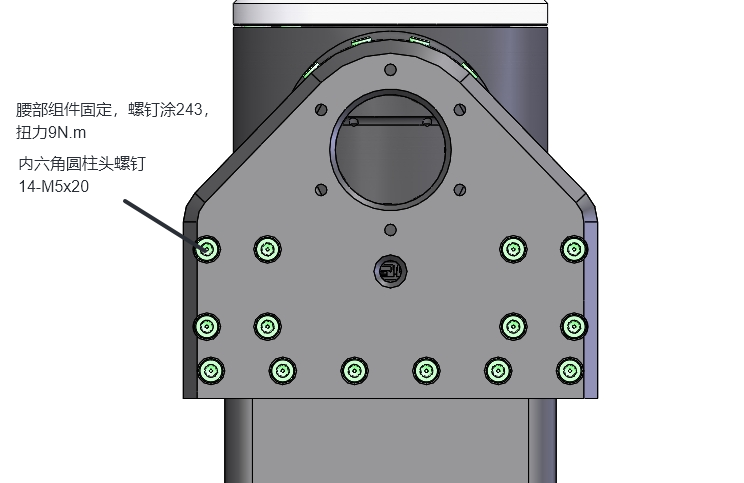
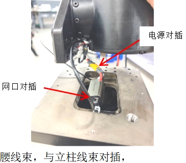
The product can be installed on a steel platform or concrete floor. Complete stand fixation, leveling, and acceptance according to the onsite delivery plan; confirm stability before proceeding.
Robot Body and Stand Installation
Inference Unit Installation
Install the inference unit in the same way as a desktop host, then connect it to the robot over Ethernet.
Storage
- Store the robot indoors in a clean, dry, ventilated environment at -10 to 45°C.
- Avoid corrosive substances, direct sunlight, fire sources, strong electromagnetic fields, and flammable or explosive materials.
- For long-term storage, place the robot in its original shipping case.
Common Tools
| Item | Part number |
|---|---|
| Hex key set | 1010507005 |
| Long screwdriver bit | 1000400066 |
| Diagonal cutter, FO-1116B | 1010409001 |
| Multimeter | 1020301003 |
| Torque wrench | 1010511005 |
| Crimping pliers | 1010040001 |
| Crimping pliers | 1010040002 |
| Ratchet wrench set with magnetic bits | 1004000031 |
| Low-cost anti-static tweezers | 1000500026 |
| Kafuter K-1668 yellow sealant | 5530030001 |
| Acetate adhesive tape | 5500400015 |
| Green Forest heavy-duty tool bag | 1001800062 |
Unboxing, Installation, and Power-Off Videos
The following videos are for delivery-operation reference. If they conflict with onsite labels, delivery-engineer instructions, or safety requirements, stop the operation and follow the onsite requirements.
Power-on video
Robot body and stand installation video
Power-off video
Operation Guide
Unboxing and Power-On
Unboxing
The robot unboxing procedure typically includes the following steps:
- Check the packaging: Before opening the box, first check whether the packaging box is damaged to ensure that the product has not been damaged during transportation.
- Remove the items: Open the packaging case and remove the robot and its accessories one by one according to the instructions in this manual, including the power supply, tools, fixtures, and other accessories.
Connect to the robot
Locate the robot’s Wi-Fi SSID under the hip roll joint. The SSID is in the format: L_v3_BOTXX.
Search for “L_v3_BOTXX” in the available Wi-Fi networks and connect to the router inside the robot body.
Note: The 5G Wi-Fi network may take longer to appear.
Each robot has a unique Wi-Fi password. Please contact the delivery engineer to obtain it.
Internal Fixed Address Modification Restriction: 192.168.8.100 is the internal fixed communication address of the robot, where the "8.100" segment is a preset fixed configuration and modification is prohibited; modification will result in abnormal robot communication and malfunction of functions.
Access the Robot Management Console
Open a browser and enter the following address: http://192.168.8.100:1888. This will open the robot control console, where you can view robot status, system information, and other related information.
Set an Access Password
Create a Password
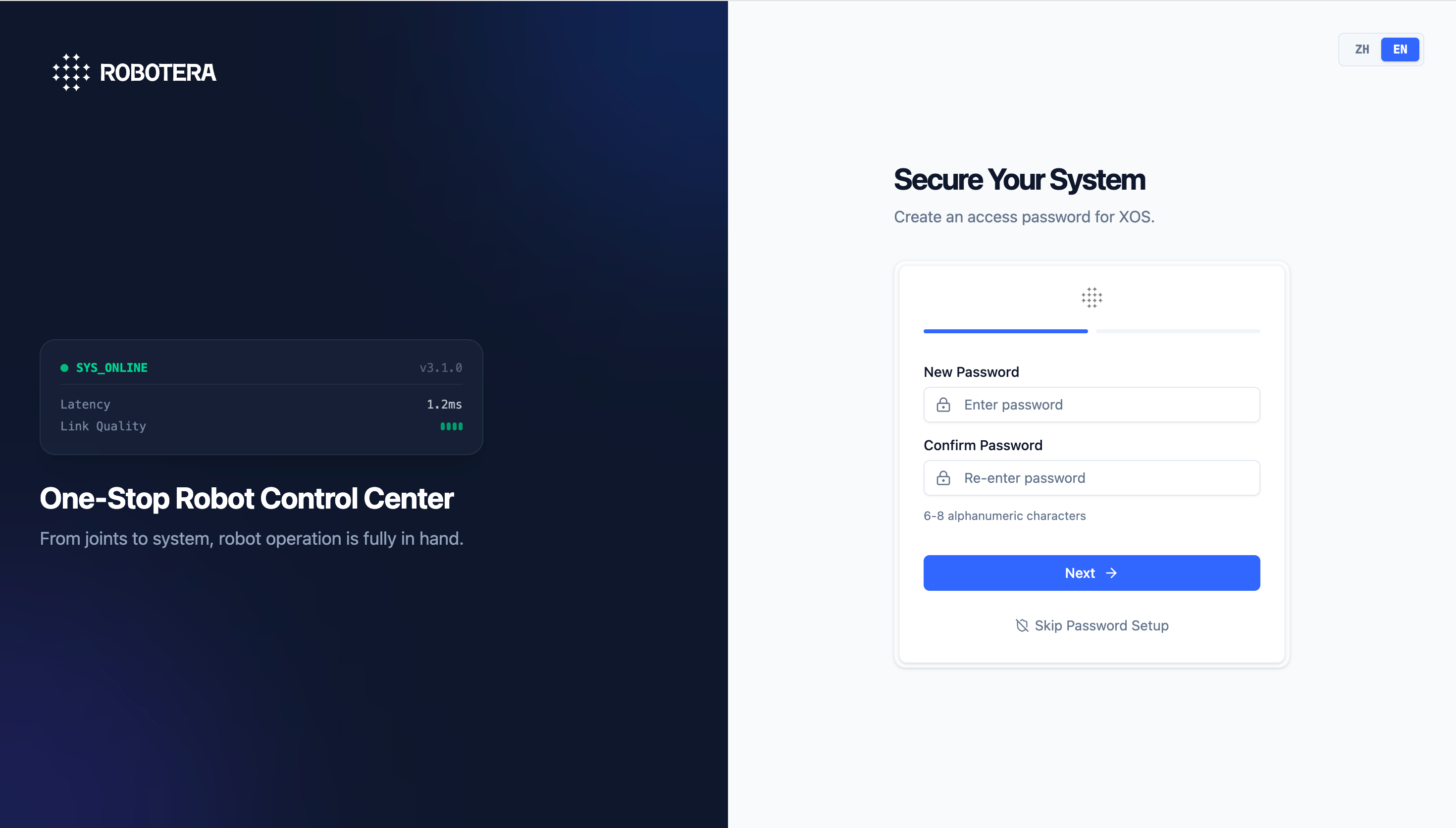
This is the initial security setup interface of XOS. It is used to configure the access password for the one-stop robot control center and ensure the security of system and device permissions.
Two-Factor Authentication
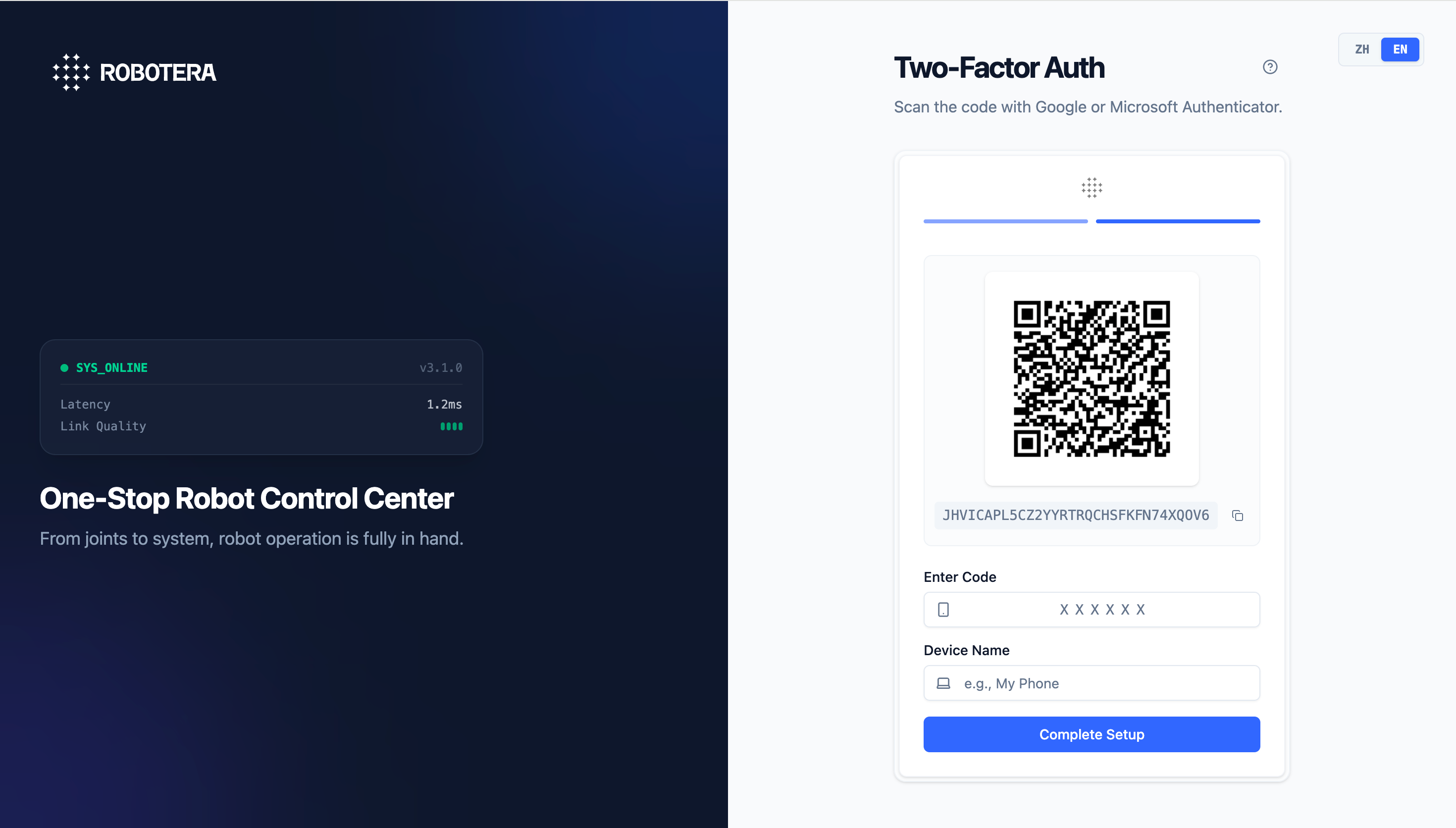
The two-factor authentication settings interface of XOS further strengthens the access security of the robot control center, providing a second layer of protection for the system beyond passwords.
Homepage
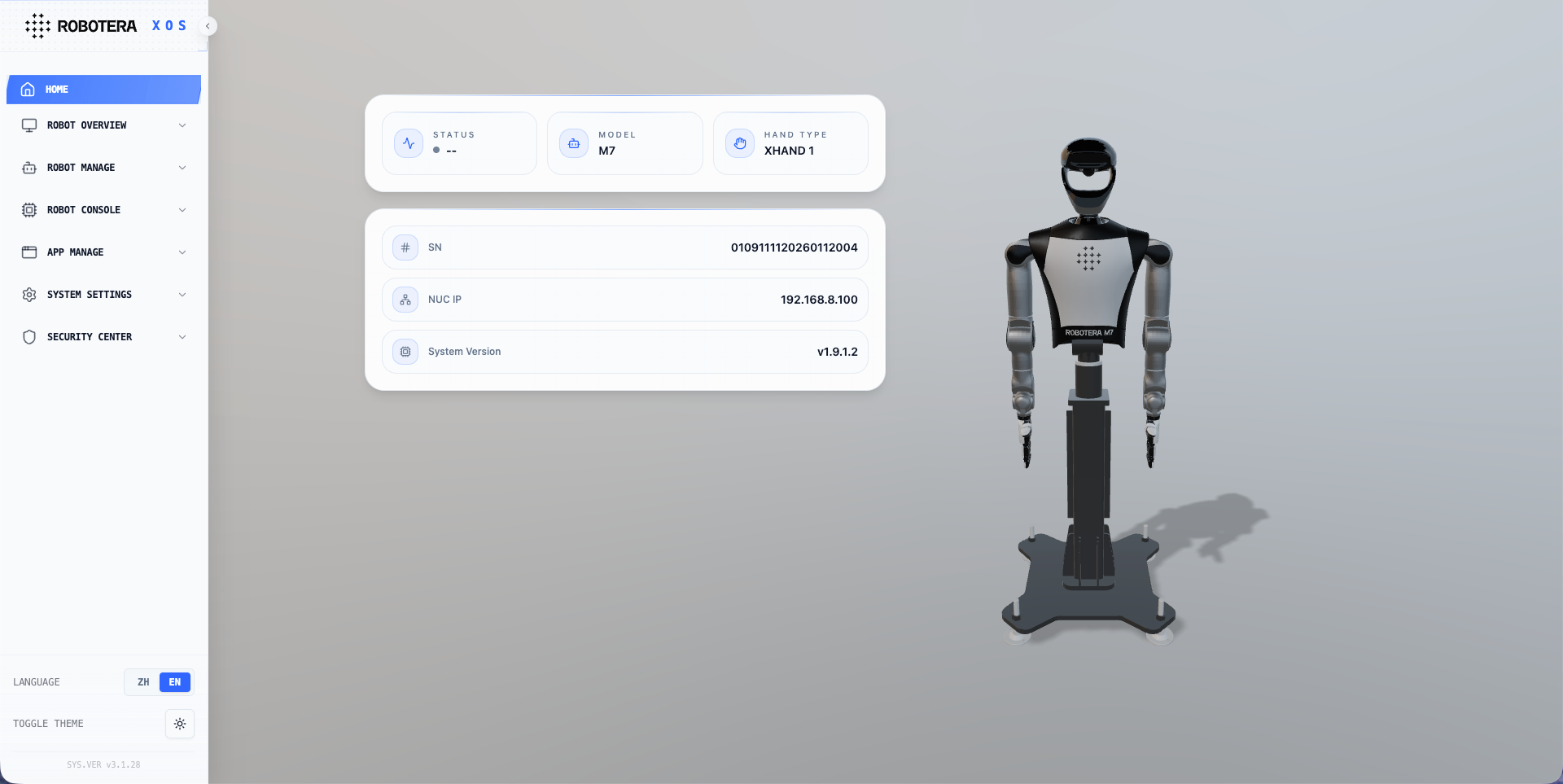
- View the overall robot status information on the home page to monitor the current robot status in real time.
- The overall robot information is displayed as follows: INIT: State after power-on startup. IDLE: Robot hardware connection state. READY: Robot initialization state. ACTIVE: The robot is ready to accept tasks. ERROR: The robot is in an error state. Robot Model: Model of the current robot. Dexterous Hand Model: Model of the dexterous hand installed on the current robot. Robot SN: Serial number of the current robot. NUC IP Address: IP address of the NUC in the current robot. XOS Version: Current XOS version of the robot. CPU Usage: Overall CPU usage curve. Robot Simulation Model: Simulation model corresponding to the current robot model.
- Real-time Error Information: If an alarm or error occurs, the corresponding joint in the robot simulation model will turn red.
Robot Overview
Log Management
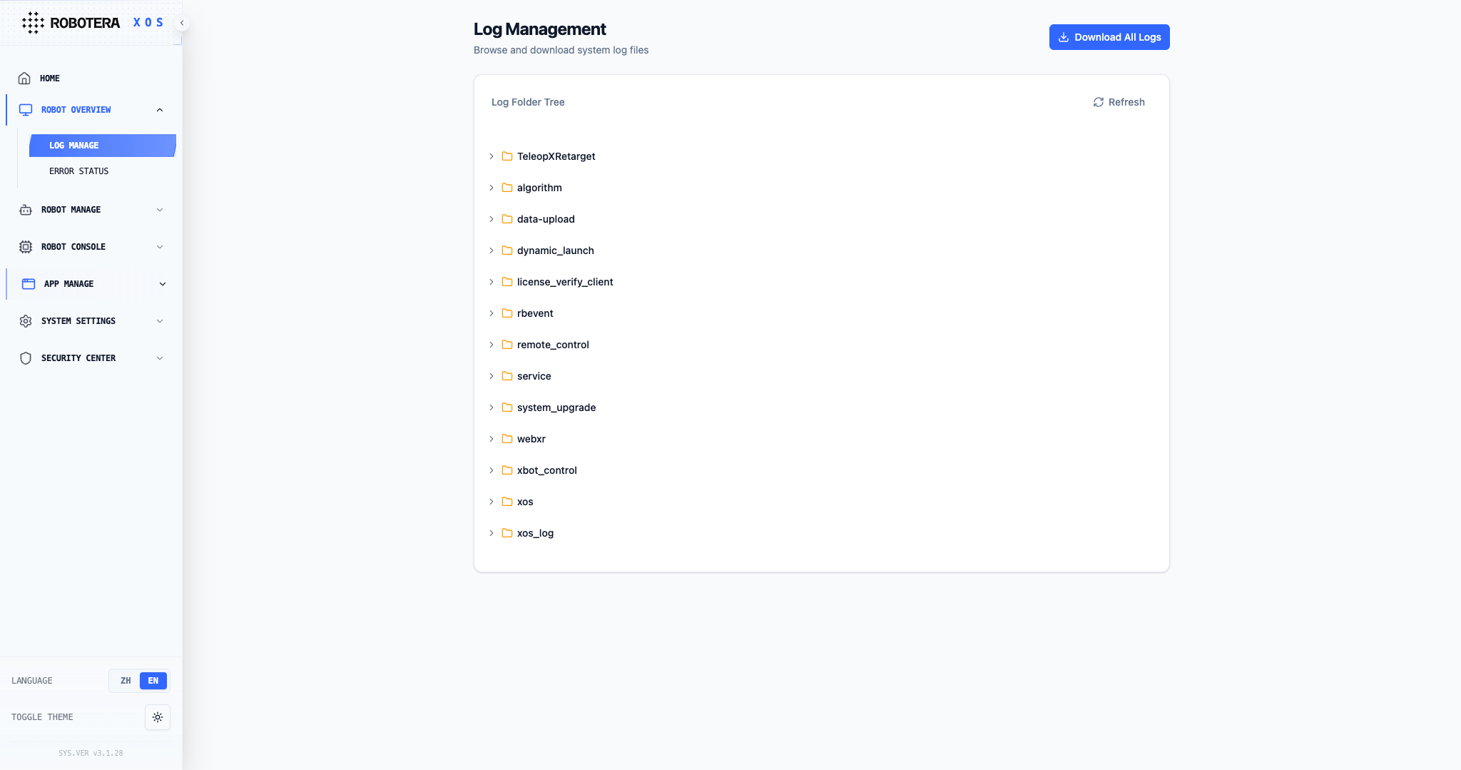
- The log management module supports log collection, storage, and visualization.
- Operation logs from each functional module can be classified and aggregated based on the system architecture hierarchy.
- The interactive interface supports log display and structured parsing.
- Users can manually download log files for specified modules according to operational needs, supporting system debugging, issue tracing, and troubleshooting.
Abnormal State
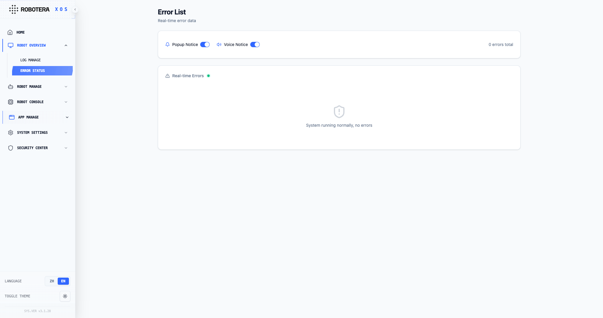
- Supports real-time monitoring of abnormal operating states of each module of the robot, supports pop-up notifications and voice announcements, and can quickly locate and handle faults.
Core Features:
- Abnormal Notification: Supports two reminder methods, pop-up notification and voice broadcast, and is enabled by default.
- Exception List: Clearly displays the exception module, name, code, location, description, and level, facilitating quick identification of issues.
- Quick Processing: Each exception provides a "View Solution" entry, which directly jumps to the corresponding handling instructions.
Operation Instructions:
- Turn on/off notifications
- Click the switch on the right side of "Pop-up Notification" or "Voice Broadcast" to toggle the on/off state.
- View exception details
- View key information such as abnormal modules, locations, and levels in the list.
- Exception levels are divided into: fatal error, serious error, error, warning, prompt, and information.
- Handle exceptions
- Click "View Solution" in the action bar on the right side of the abnormal row to obtain the official processing steps.
Robot Management
Sound Settings
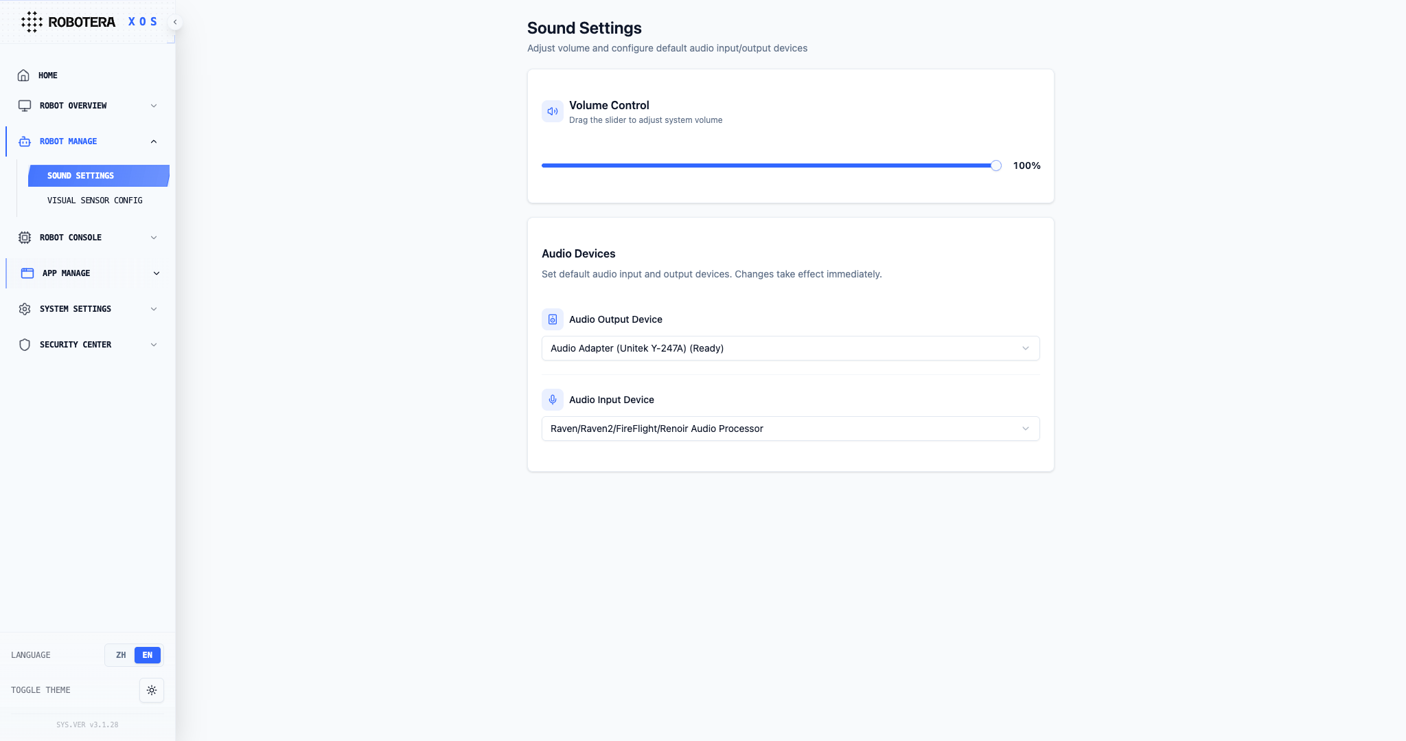
- This function supports a volume adjustment range of 0-100%. Users can precisely control the robot's sound volume by sliding the adjustment bar or using the plus/minus buttons. By default, the system remembers the last settings parameters and automatically restores the user's preferred settings after restarting.
- Supports users to independently select the audio output device of the robot. The system will automatically scan and list the currently available sound card list (including built-in sound cards, external USB sound cards, etc.), and the output device can be quickly switched via the drop-down menu.
Visual Sensor Configuration
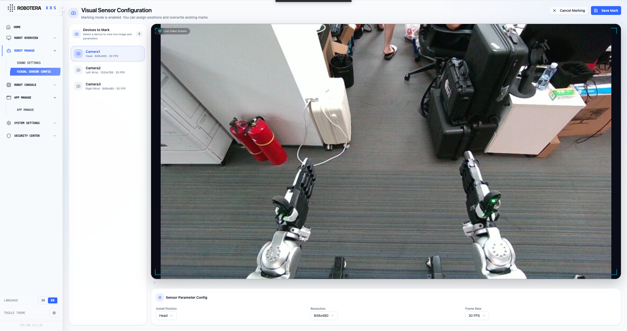
Provides a visual configuration interface for camera sensors. Supports full camera labeling with installation positions at the head, left wrist, and right wrist. Resolution and frame rate can be configured manually; changes take effect after restarting the camera. Designed for flexible multi-camera management.
Robot Control Console
Refer to the detailed usage method in xviz usage documentation.
Integrated Data Center
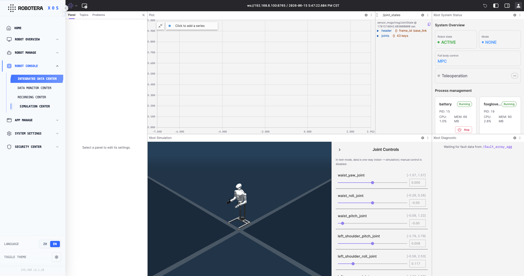
The XOS Robot Console – Integrated Data Center is a one-stop data visualization and simulation debugging platform designed for robot users. It supports real-time monitoring of operational data such as robot joint status, as well as fault diagnosis, data recording, and simulation validation. It provides end-to-end support for robot debugging, operation analysis, and issue localization.
Data Monitoring Center
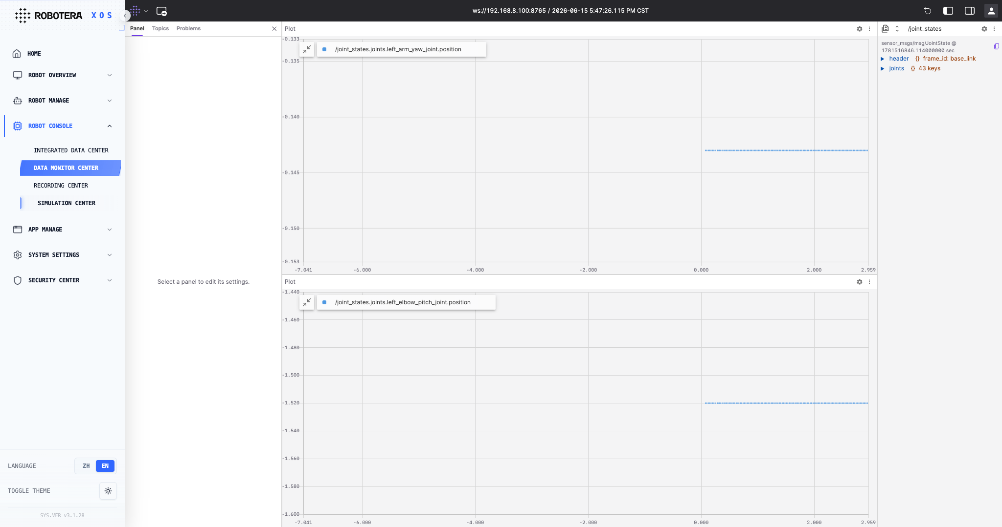
The XOS Data Monitoring Center is a real-time visualization dashboard for robot operation data. It supports real-time acquisition and visualization of key data streams, such as joint status data, including arm and elbow joint positions, through line charts and other visual formats. This helps users intuitively monitor the robot’s operating status and quickly identify data anomalies and fluctuations.
Recording Center
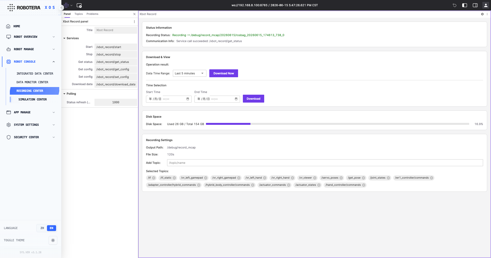
- Enables flexible subscription to ROS topics, including XOS-specific topics, as well as custom recording and export by time range. It supports one-click quick export and precise time-range export, adapts to the XOS data format and the small-screen layout of portable devices, and simplifies data acquisition and export operations.
Simulation Center
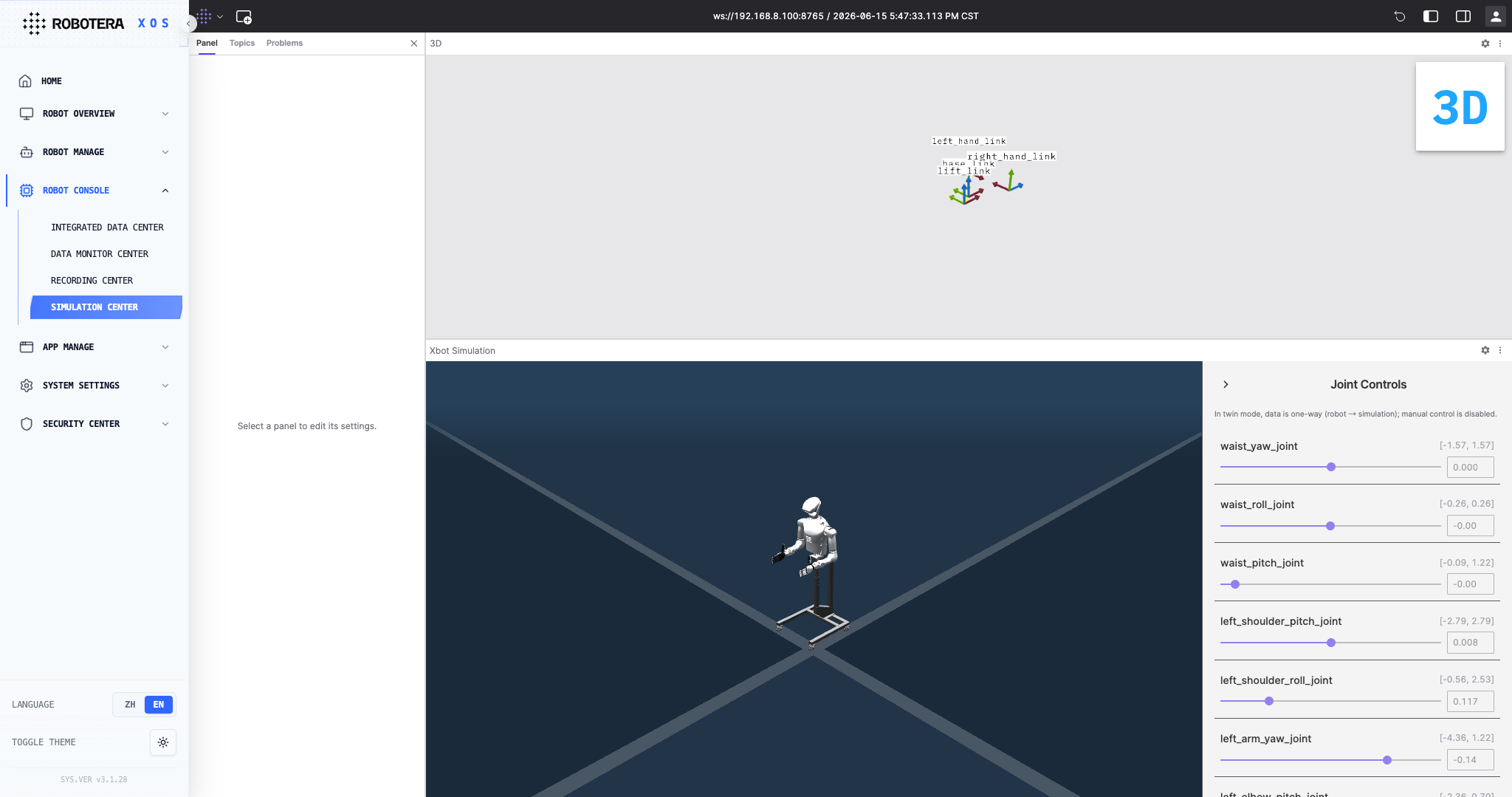
XOS Simulation Center – Twin Mode links the robot’s real-world operating data with a virtual model in real time, enabling visual debugging and validation through virtual-real synchronization. It supports real-time mapping of joint states, motion trajectory replay, and physics-based simulation validation. This helps developers verify control logic, identify potential risks in advance, and improve debugging efficiency and safety.
System Settings
Robot Info
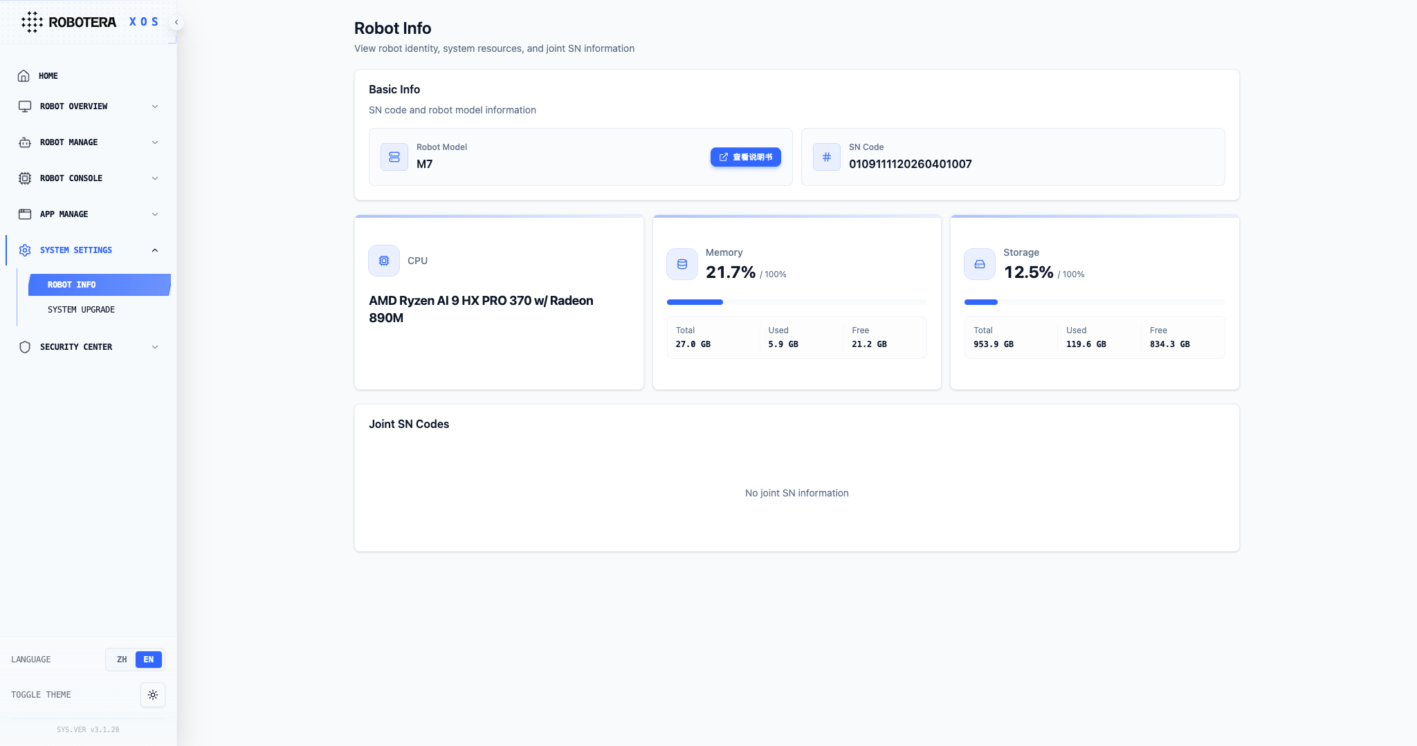
- Basic Info: View the robot model and full-unit SN code, which is required for after-sales and warranty service. Click "View Manual" to access the complete manual.
- Resource Status: Monitor CPU, memory, and storage usage to determine whether the system load is normal.
- Joint SN Codes: Unique identifiers for all motion joints. Required when repairing or replacing joints.
exclamation Note: Do not modify SN codes. If storage or memory usage is too high, contact operations.
System Upgrade
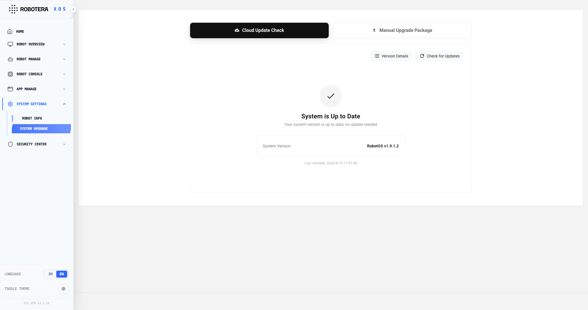
- This function is used to manage the software versions of the robot system and the dexterous hand controller. It supports both cloud-based update checking and manual upgrade.
- Users can view the current system version, RobotOS, and the version details of each module.
- The page supports checking for updates, downloading upgrade packages, manually uploading upgrade packages, and starting the upgrade after the robot is stationary, the battery level is sufficient, or an external power source is connected.
exclamation The robot will restart automatically during the upgrade. Do not operate or power off the robot during this process.
Security Center
For specific usage instructions, please refer to the User Manual – XOS Security Section.
Set Password
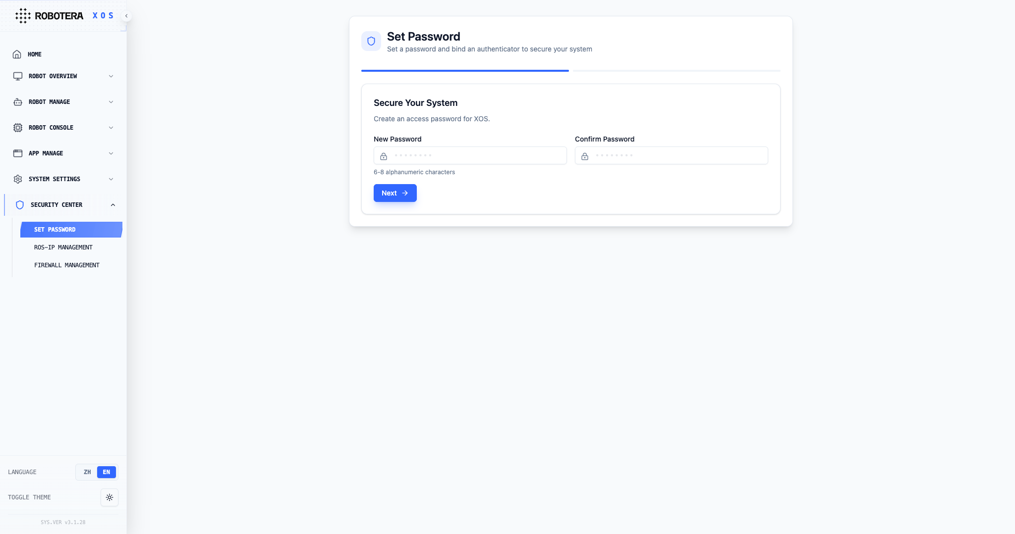
The Set Password function of the XOS Security Center supports users to update their login password (6-8 characters, letters or numbers), and can also turn off password protection to achieve flexible management of access rights to the Robot Control Center.
Authenticator Management
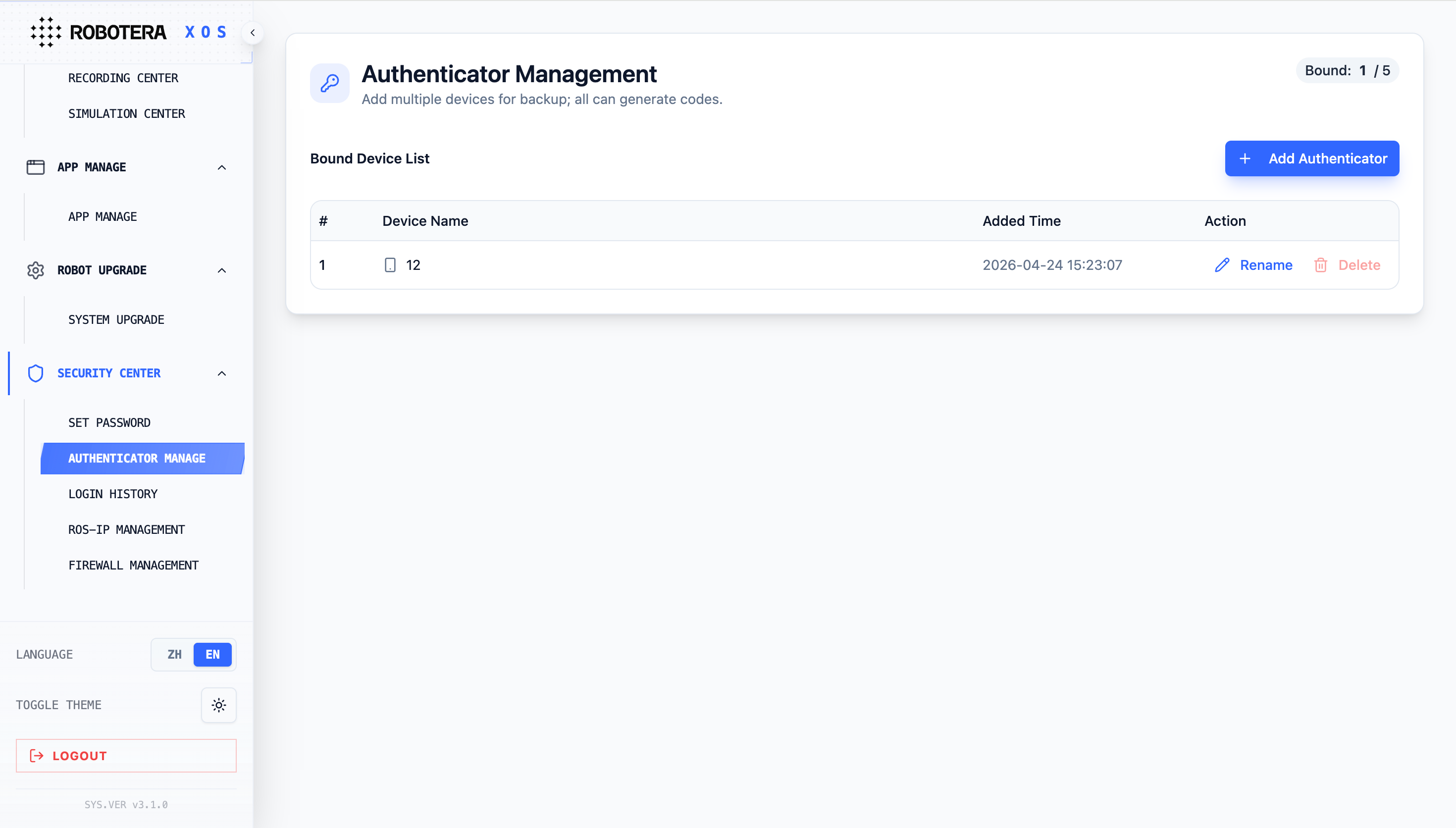
The Authenticator Management feature of XOS Security Center supports users in adding, renaming, and deleting TOTP verification devices, with a maximum of 5 devices that can be bound, facilitating users to flexibly manage backup devices for two-factor authentication and ensuring the security of system access.
Login History
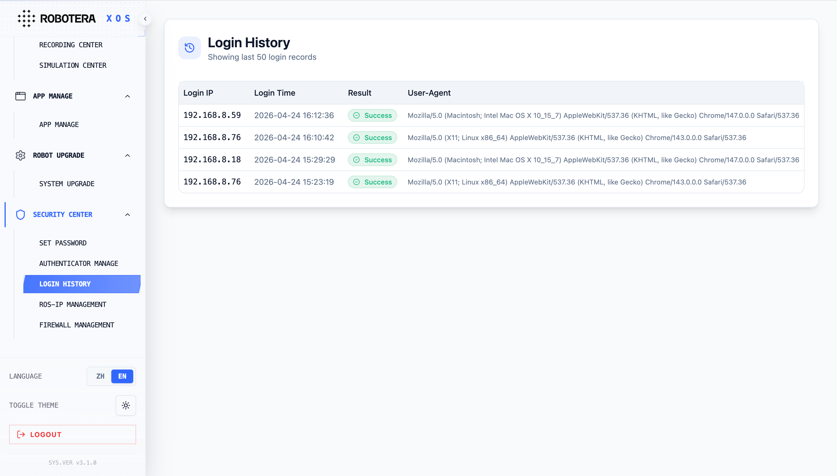
The Login History feature of the XOS Security Center can display the latest 50 login records, including login IP, time, result, and client information, helping users trace access behavior and promptly detect abnormal login risks.
ROS-IP Management
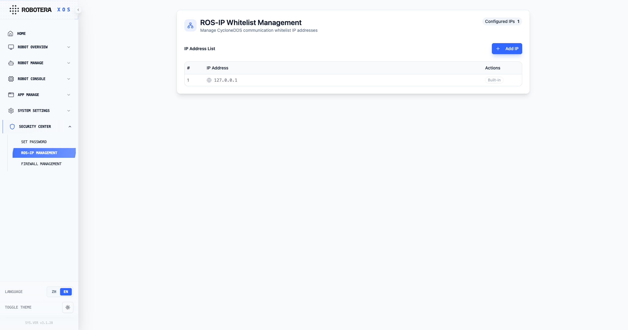
ROS-IP Allowlist Management function of XOS Security Center is used to configure trusted IP addresses for CycloneDDS communication, supports adding and deleting IPs, and only allows devices within the allowlist to communicate with the robot system, enhancing the security and controllability of ROS communication.
Firewall Management
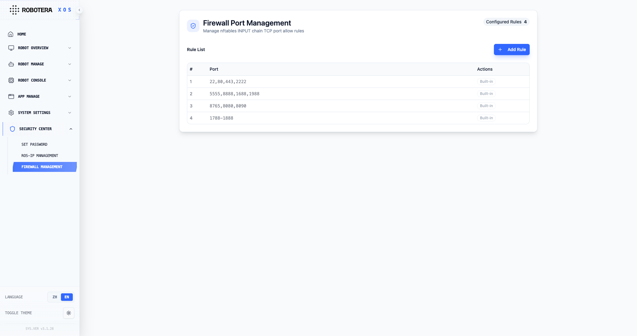
The firewall management function of the XOS Security Center is used to manage the port allowing rules of the nftables INPUT chain, supports viewing system built-in rules and customs adding new rules, controls network port access of the robot system, and strengthens network security protection.
Emergency Stop
M7 provides an emergency stop remote control to promptly cut off power in case of unexpected situations, ensuring safety.
The following figure shows the emergency stop remote control:
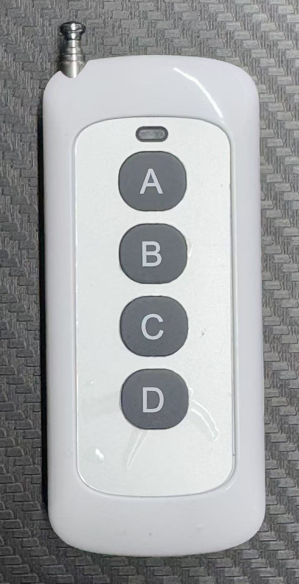
Press the A button once to turn off the power of the onboard computer, and press it again to restore it
Press the D button once to turn off the power of the joint motor, and press it again to restore it
exclamation Important: Keep the emergency stop remote control ready during debugging. In an emergency, press D to cut power to the joint motors.
Maintenance, Troubleshooting, and After-Sales Service
Maintenance
Maintenance is preventive work performed periodically while the robot is functioning normally. Its purpose is to keep the robot intact and fit for operation, maintain it in good condition, identify and eliminate potential faults promptly, and keep it orderly, clean, lubricated, and safe.
Personnel responsible for maintaining the robot must use this manual together with local conditions and actual operating conditions to establish an appropriate maintenance schedule. They must perform routine inspections and maintenance and address faults promptly.
Scheduled Cleaning
The robot and its operating area must be cleaned regularly to avoid affecting normal operation. Before cleaning, ensure that the robot is powered off, the emergency-stop button is released, and the charging cable is disconnected.
Cleaning tools: a soft, clean, lint-free cloth; a soft-bristle brush; water, alcohol, or an amino-based cleaning substance; and lens-cleaning paper.
Cleaning primarily covers the robot surface, buttons, cameras, interfaces, and similar areas.
| Item | Cleaning Method |
|---|---|
| Robot surface | Wipe the robot surface with a slightly damp cloth, then dry it with a dry cloth. |
| Cameras | Use lens-cleaning paper to remove dust and other debris from the head and wrist cameras. |
| Buttons | Use a soft-bristle brush to remove dust and debris from the button recesses, wipe the button surfaces with a slightly damp cloth, and then dry them with a dry cloth. |
| Interfaces | Use a soft-bristle brush to remove dust and debris from interface recesses, then wipe the interfaces clean with a dry cloth. |
Monthly Maintenance
| Item | Maintenance Requirement |
|---|---|
| Appearance | Remove dust and debris from the robot body and keep it clean. A soft, lint-free, slightly damp cloth may be used on the robot surface. |
| Inspect the robot housing for defects. | |
| Check whether any screws or nuts on the arms, waist, or wrists are missing or loose. Replace missing fasteners and tighten loose ones. | |
| Function | Check overall robot operation and verify that there are no abnormal noises, vibrations, or other abnormalities. |
| Components | Check whether the leveling-foot nuts are loose and ensure that the feet are secure. |
| Check whether the leveling feet have shifted at their mounting positions and caused robot displacement. | |
| Visually inspect the wrist housing, connectors, links, and similar parts for damage. | |
| Remove dust and debris from the cameras and confirm visually that they are clean. |
Quarterly Maintenance
| Item | Maintenance Requirement |
|---|---|
| Arm-axis joint modules and bearings | With power on, exercise each joint module individually within its motion range and check for abnormal noise or vibration. With power off, move each joint module slightly by hand and check joint-module backlash and bearing clearance. With power off, move each joint module slowly through a larger range by hand and check for abnormal noise and uneven resistance. |
| Wrist connecting rods | With the robot stationary, inspect the wrist connecting rods for deformation or cracks. |
Common Fault Handling
Mechanical or environmental factors may cause abnormalities while the robot is operating. These can generally be resolved through recovery mode or a restart. This section lists common faults for onsite reference.
If a fault remains after following the instructions in the troubleshooting tables, or if disassembly or component replacement is required, contact Robotera or technical support authorized by Robotera.
General Fault Recovery
Notice
When a robot fault occurs, first try the following procedure to perform an initial recovery. At the same time, record the fault symptoms by taking photos or videos, save the relevant log files, and then follow the handling steps for the specific fault.
Restart the robot as follows:
Turn off the power switch on the lower part of the robot by moving it downward.
Wait five seconds, then turn the power switch back on by moving it upward.
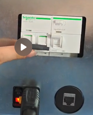
Wait several seconds for the robot to restart automatically.
If restarting does not clear the fault, contact Robotera or technical support authorized by Robotera.
System Faults
| Fault Code | Description | Corrective Action |
|---|---|---|
| System lag | Check network communication quality. | |
| Router Wi-Fi disconnects | Check whether the power supply, address, and configuration are correct. | |
| Poor or interrupted communication during teleoperation | Check communication quality and try replacing the network cable. | |
| Teleoperation cannot return to the initial position | Restart and check whether normal operation is restored. | |
| Poor communication between the main controller and power board | Replace the communication cable. | |
| 6102001 | Motion-control frequency is too low | |
| 6101002 | Motion-control module crashed or is unresponsive | |
| 6101003 | Behavior-control module crashed or is unresponsive | |
| 6101004 | Monitoring module crashed or is unresponsive | |
| 6101005 | Diagnostic module crashed or is unresponsive | |
| 6101006 | Network interface unavailable | |
| 6101007 | No available slave detected | Check whether the power supply is normal. |
Model Faults
| Fault Code | Description | Corrective Action |
|---|---|---|
| Inference execution interrupted | ||
| Runaway motion | ||
| 1901001 | Robot has fallen; body tilt exceeds the limit | Return the robot to a normal state, then repeat the operation. |
| 1903012 | Abnormal MPC trajectory planning; trajectory oscillation | |
| 1902003 | Model inference is too slow | If computing resources are insufficient, shut down and restart. |
| 1902009 | Used to identify which joint experienced a collision | Stop the motion and restore the factory motion. |
| Robot stops unexpectedly while executing a task |
Joint-Module Faults
| Fault Code | Description | Corrective Action |
|---|---|---|
| Joint-module communication disconnected | Check the harness or replace the module. | |
| Joint-module overtemperature | Check whether the joint has reached its limit position or replace the module. | |
| Joint step-change fault | ||
| Joint lag or sticking | Replace the module. | |
| Joint low-voltage fault | Check the power supply and harness, or replace the module. | |
| 1201011 | Joint-module encoder fault | 1. Power off and restart. 2. Configure the parameters with technical support or replace the module. |
| 1201012 | Joint-module overcurrent protection | This may occur during high-amplitude motions. Power off and restart. |
| 1201013 | Joint-module internal-state error | Perform internal initialization. |
| 1201014 | Joint-module stall | Replace the module and return it for repair. |
| 1201015 | Joint-module EtherCAT communication error | Check whether the interface cable is properly connected, whether the interface device is correct, and whether there is a system issue such as a network-adapter fault. |
| 1201016 | Joint-module DRV error | Restart or power off and restart. |
| 1201018 | Joint connection error | Check the harness. |
| 1201019 | Joint startup failed | |
| 1201020 | Joint-mode switching failed | Check switching between Boot initialization mode and normal App operating mode. |
| 1201021 | Joint communication abnormal | Follow the joint-communication fault procedure. |
Harness Faults
| Fault Code | Description | Corrective Action |
|---|---|---|
| Wrist-camera harness disconnected | ||
| Wrist communication harness disconnected | ||
| Wrist power-supply harness disconnected | ||
| Arm joint offline |
Encoder Faults
| Fault Code | Description | Corrective Action |
|---|---|---|
| 1301001 | Magnet installation or encoder-circuit issue | |
| 1301002 | The module's internal storage does not contain the parameters required to calculate the zero position, or the module has not been zeroed | |
| 1301004 | Failed to calculate the encoder initial value; the module stator may not be stationary or the encoder data may be fluctuating significantly | |
| 1301005 | During startup, the module rotor may not be stationary or the encoder data may be fluctuating significantly | |
| 1301006 | The module reduction-ratio parameter may be incorrect, preventing zero-position calculation | |
| 1301007 | The calculated multi-turn value is invalid | |
| 1301008 | The number of encoder error flags read by the motor-side encoder exceeds the threshold | |
| 1301009 | The number of motor-side encoder CRC errors exceeds the threshold (default: 5,000), possibly due to communication interference | |
| 1301010 | The motor-side encoder packet-loss rate exceeds the threshold (default: 10%), possibly due to communication interference or a communication-cable connection problem |
Camera Faults
| Fault Code | Description | Corrective Action |
|---|---|---|
| 2101001 | RealSense cannot connect | Check the harness and main-controller port. |
| 2101002 | RealSense data-stream interruption |
NUC Faults
| Fault Code | Description | Corrective Action |
|---|---|---|
| 1702001 | Temperature exceeds the normal threshold (70–80°C) | |
| 1701002 | Temperature exceeds the maximum threshold (100°C) |
Storage
Before long-term storage, power off the robot, clean it, and inspect its exterior. Store it indoors in a clean, dry, ventilated environment at -10 to 45°C. Keep it away from corrosive substances, direct sunlight, fire sources, strong electromagnetic fields, and flammable or explosive materials. For extended storage, use the original shipping case. Before reuse, inspect the exterior, cables, fasteners, and functions.
After-Sales Warranty
Warranty Policy
- For the complete robot and related products, the warranty period begins on the date the goods are signed for and accepted. If a non-user-caused performance fault occurs during normal use within the warranty period, Robotera will provide the corresponding repair or component replacement free of charge.
- Warranty periods for major components:
| Type | Coverage | Warranty Period |
|---|---|---|
| Main unit | Robot main unit and its constituent parts | 1 year |
| Actuation components | Joint motors and similar components | 1 year |
| Accessories | Power adapter and similar accessories | 1 year |
- During the warranty period, unauthorized modification, disassembly, or opening of the enclosure will immediately invalidate the warranty.
- If the product is outside the warranty period, support remains available as a separately purchased service. Repair fees are charged according to Robotera's applicable rates.
Warranty Exclusions
- The warranty period has expired.
- Damage was caused by failure to follow the user manual.
- Damage was caused by improper use or operating error.
- Damage was caused by human action or an accident.
- Damage was caused by unauthorized modification, disassembly, enclosure opening, installation of additional components, repair, or component replacement.
Repair-Service Responsibilities
- The customer is responsible for losses caused by an incorrect delivery address supplied by the customer or by the recipient refusing delivery.
- After receiving a product submitted for warranty service, Robotera will inspect it to determine the cause. If the issue is confirmed to be a product-quality defect, Robotera will cover the inspection, materials, labor, and return-shipping costs. If the product does not qualify for free repair, the customer may choose paid repair or return of the unrepaired product; the customer is responsible for return shipping in the latter case.
- If the issue is outside warranty coverage, Robotera will still provide repair service but will charge applicable inspection, replacement-part, testing, labor, and transportation fees based on the specific issue.
- Repair may result in data loss. Back up all data in advance; the customer is responsible for consequences resulting from failure to do so.
- To provide necessary after-sales support, Robotera may access the customer's equipment. Repair may involve system operation and access to logs; by requesting service, the customer authorizes Robotera to perform this access.
- During the warranty period, damaged components removed during replacement become the property of Robotera, and the replacement components become the property of the customer. Outside the warranty period, removed damaged components remain the property of the customer.
- Robotera does not authorize third parties to provide repair services. Contact Robotera directly for after-sales service.
- Contact Robotera for any additional information about warranty service.
Development Guide
Overall robot software architecture
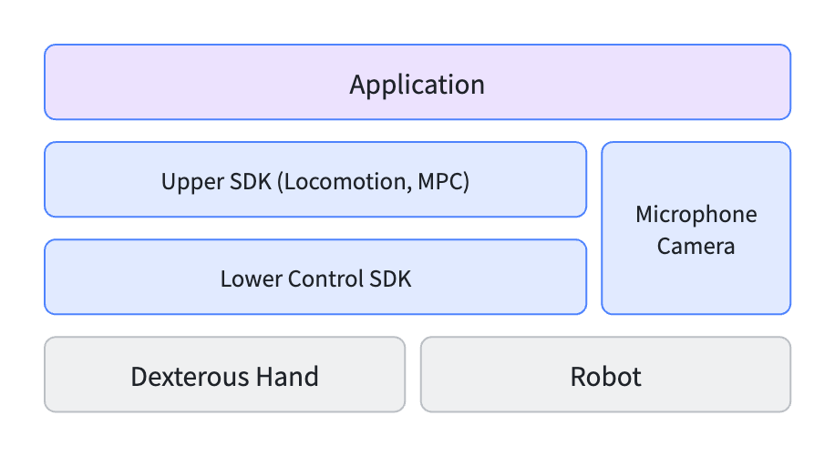
Joint Axis
SDK Call Instructions
M7 uses ROS2 Humble to interact with the entire machine. Developers can connect to the robot via wired/wireless networks, or communicate with the host system by logging into the developer container to write and run programs.
Ros2 domain: 211
If you wish to connect to the robot via another host for control:
- Connect to the robot via a wired connection or directly connect to the robot's WIFI
- Prerequisite: The host has a ros-humble + cyclonedds environment
- Messages used by the robot need to be deployed on its own host
git clone https://github.com/roboterax/teleop_client.git
cd teleop_client
colcon build
source install/setup.bash- Set environment variables
export ROS_DOMAIN_ID=211
export RMW_IMPLEMENTATION=rmw_cyclonedds_cpp- Configure unicast, and directly execute the following command on the host:
sudo mkdir /etc/xbot/
sudo tee /etc/xbot/cyclonedds.xml > /dev/null << 'EOF'
<?xml version="1.0"?>
<CycloneDDS xmlns="https://cdds.io/config">
  <Domain id="211">
    <General>
      <AllowMulticast>false</AllowMulticast>
    </General>
    <Discovery>
      <Peers>
        <Peer address="127.0.0.1"/>
        <Peer address="192.168.8.100"/>
      </Peers>
      <ParticipantIndex>auto</ParticipantIndex>
      <MaxAutoParticipantIndex>300</MaxAutoParticipantIndex>
    </Discovery>
  </Domain>
</CycloneDDS>
EOF

export CYCLONEDDS_URI=file:///etc/xbot/cyclonedds.xml
ros2 daemon stop
ros2 daemon start- Set the ROSIP allowlist on Robot-XOSROSIP设置说明文档
- Simply add the host IP to the xos ros allowlist
- Jump directly to the
**Underlying Joint Control SDK **section
Robot Port Usage Specification
Port Usage Prohibited
Commonly used built-in ports for system reserved ports:
tcp dport { 22, 80, 443, 2222 } accept
tcp dport { 5555, 8888, 1688, 1788, 1888, 1988 } accept
tcp dport { 8765, 8080, 8090 } accept
tcp dport 1788-1888 accept
Developer Available Ports
Only:1024 ~ 65535
Enter the developer container
Username: developer
Initial Password: developer
Port Number: 2222
ssh developer@192.168.8.100 -p 2222 #SSH into the robot backend and enter the workspace.Underlying Joint Control SDK
Joint Control Process
flowchart TD
    A[Check robot hardware status<br>(Confirm EtherCAT connection, joint power-on,<br>green power light is on)] --> B{Select mode}
    B -->|Full-body mode (with XHAND)| C[Start low-level joint control service<br>/dynamic_launch<br>launch_mode: 'pos']
    B -->|Full-body mode(without XHAND)| C2[Start low-level joint control service<br>/dynamic_launch<br>launch_mode: 'no_hand_pos']
    C & C2 --> D[Initialize joint control service<br>/ready_service<br>(Wait about 20 seconds, interface returns success)]
    D --> E[Move joints to standard start position<br>/simple_trajectory]
    E -->|Enable control| G1[Enable control<br>/activate_service]
    G1 --> H[Send joint control command<br>]
    H --> I[Stop low-level joint control service<br>/stop_launch]
Overall Robot Joint Name
The joint list is as follows, and the overall structure refers to the product structure diagram
Joint Name
- left_shoulder_pitch_joint
- left_shoulder_roll_joint
- left_arm_yaw_joint
- left_elbow_pitch_joint
- left_elbow_yaw_joint
- left_wrist_pitch_joint
- left_wrist_roll_joint
- neck_yaw_joint
- neck_pitch_joint
- right_shoulder_pitch_joint
- right_shoulder_roll_joint
- right_arm_yaw_joint
- right_elbow_pitch_joint
- right_elbow_yaw_joint
- right_wrist_pitch_joint
- right_wrist_roll_joint
- waist_pitch_joint
- waist_yaw_joint
XHAND Joint Name
- left_hand_thumb_bend_joint
- left_hand_thumb_rota_joint1
- left_hand_thumb_rota_joint2
- left_hand_index_bend_joint
- left_hand_index_joint1
- left_hand_index_joint2
- left_hand_mid_joint1
- left_hand_mid_joint2
- left_hand_ring_joint1
- left_hand_ring_joint2
- left_hand_pinky_joint1
- left_hand_pinky_joint2
- right_hand_thumb_bend_joint
- right_hand_thumb_rota_joint1
- right_hand_thumb_rota_joint2
- right_hand_index_bend_joint
- right_hand_index_joint1
- right_hand_index_joint2
- right_hand_mid_joint1
- right_hand_mid_joint2
- right_hand_ring_joint1
- right_hand_ring_joint2
- right_hand_pinky_joint1
- right_hand_pinky_joint2
XHAND 1 Pro Joint Name
- left_hand_thumb_bend_joint
- left_hand_thumb_rota_joint1
- left_hand_thumb_rota_joint2
- left_hand_thumb_rota_joint3
- left_hand_index_bend_joint
- left_hand_index_rota_joint1
- left_hand_index_rota_joint2
- left_hand_index_rota_joint3
- left_hand_mid_bend_joint
- left_hand_mid_rota_joint1
- left_hand_mid_rota_joint2
- left_hand_mid_rota_joint3
- left_hand_ring_bend_joint
- left_hand_ring_rota_joint1
- left_hand_ring_rota_joint2
- left_hand_ring_rota_joint3
- left_hand_pinky_bend_joint
- left_hand_pinky_rota_joint1
- left_hand_pinky_rota_joint2
- left_hand_pinky_rota_joint3
- left_hand_ltspalm_joint
- right_hand_thumb_bend_joint
- right_hand_thumb_rota_joint1
- right_hand_thumb_rota_joint2
- right_hand_thumb_rota_joint3
- right_hand_index_bend_joint
- right_hand_index_rota_joint1
- right_hand_index_rota_joint2
- right_hand_index_rota_joint3
- right_hand_mid_bend_joint
- right_hand_mid_rota_joint1
- right_hand_mid_rota_joint2
- right_hand_mid_rota_joint3
- right_hand_ring_bend_joint
- right_hand_ring_rota_joint1
- right_hand_ring_rota_joint2
- right_hand_ring_rota_joint3
- right_hand_pinky_bend_joint
- right_hand_pinky_rota_joint1
- right_hand_pinky_rota_joint2
- right_hand_pinky_rota_joint3
- right_hand_ltspalm_joint
Note: The KP and KD values vary by hand type. Please refer to the relevant hand documentation.
Joint Control Instructions
Control Mode
The M7 system does not have lower limb, upper limb support including the waist torque control mode and position control mode. Differentiated by different startup methods
Under different startup modes
- For joints with torque control, only the following parameters can be set:
- velocity: Joint target velocity
- position: Joint target position
- feedforward: Feedforward force
- kp: Proportional Gain
- kd: Differential Gain
- For joints with position control, only the position (target position of each joint) parameter needs to be set. The remaining parameters include:
- velocity: Joint target velocity
- feedforward: feedforward force or torque
- kp: Proportional Gain
- kd: Differential Gain
The above parameters do not take effect in position control mode. Please ensure that only the position field is filled to avoid redundant data or misuse of the interface.
Control Frequency
The joint control frequency of L3 can reach 500Hz, and the control frequency of the dexterous hand is 83Hz (serial data)
Brake
The robot is equipped with a brake mechanism at the joints in the pitch and yaw directions of the waist.
- When entering position control mode, the brakes of these joints will automatically release, allowing the joints to move freely; when the control ends or the system is powered off, the brakes will automatically close to ensure the posture safety and mechanical stability of the robot in the non-control state.
- Before entering the PD mode, the brake needs to be manually released. The command to release the brake is as follows:
# Release brake
ros2 service call /control_brake xbot_common_interfaces/srv/SetJointIntegerParam "joint_name: ['waist_pitch_joint']
param_value: [1]"

ros2 service call /control_brake xbot_common_interfaces/srv/SetJointIntegerParam "joint_name: ['waist_yaw_joint']
param_value: [1]"

# Engage brake
ros2 service call /control_brake xbot_common_interfaces/srv/SetJointIntegerParam "joint_name: ['waist_pitch_joint']
param_value: [0]"

ros2 service call /control_brake xbot_common_interfaces/srv/SetJointIntegerParam "joint_name: ['waist_yaw_joint']
param_value: [0]"
This mechanism does not require manual intervention from users, is automatically managed by the system, and is applicable to scenarios of normal start-stop and abnormal power outage.
Underlying joint control interface
1. Joint Control Command Interface
| Interface Name | Type | Function Description | Message Type |
|---|---|---|---|
/hybrid_body_controller/commands | ROS2 Topic | Issue joint control commands | xbot_common_interfaces/msg/HybridJointCommand |
xbot_common_interfaces/msg/HybridJointCommandParameter Description:- header: Standard message header (including timestamp and frame_id)
- joint_name: string[], list of joint names, corresponding to each control joint
- position: float64[], target position (rad) of each joint
- velocity: float64[],target velocity (rad/s) for each joint
- feedforward: float64[], feedforward force or torque (N·m)
- kp: float64[], proportional gain for each joint
- kd: float64[], current force/torque of differential gain for each joint
2. Hand Joint Control Command Interface
| Interface Name | Type | Function Description | Message Type |
|---|---|---|---|
/hand_controller/commands | ROS2 Topic | Issue joint control commands | xbot_common_interfaces/msg/HybridJointCommand |
xbot_common_interfaces/msg/HybridJointCommandParameter Description:- header: Standard message header (including timestamp and frame_id)
- joint_name: string[], list of joint names, corresponding to each control joint
- position: float64[], target position (rad) of each joint
- velocity: float64[],target velocity (rad/s) for each joint
- feedforward: float64[], feedforward force or torque (N·m)
- kp: float64[], proportional gain for each joint
- kd: float64[], current force/torque of differential gain for each joint
3. Joint Status Interface
| Interface Name | Type | Function Description | Message Type |
|---|---|---|---|
/joint_states | ROS2 Topic | Publish joint state command | sensor_msgs/msg/JointState |
sensor_msgs/msg/JointStateParameter Description:- header: Standard message header (including timestamp and frame_id)
- name: string[], all joint names
- position: float64[], target position (rad) of each joint
- velocity: float64[],target velocity (rad/s) for each joint
- effort: float64[], joint torque (N·m)
4. Hand Sensor Status Interface
XHAND
| Interface Name | Type | Function Description | Message Type |
|---|---|---|---|
/hand_sensor | ROS2 Topic | Publish joint state command | xbot_common_interfaces::msg::XhandHandSensor |
xbot_common_interfaces::msg::XhandHandSensorParameter Description:- header: standard message header (including timestamp and frame_id)
- hand_type: string[], hand type
- fx: int8[], force in the x direction of the fingers, unit 0.1 N
- fy: int8[], force in the y direction of the fingers, unit 0.1 N
- fz: int8[], force in the z direction of the fingers, unit 0.1 N
- temperature: uint8[], finger temperature, degrees Celsius
- calc_temperature: uint8, calculated temperature, degrees Celsius
Each Sensor contains 121 groups of fx, fy, and fz data: the first group is the resultant force, and the remaining 120 groups are component forces arranged as 10 * 12.
There are 5 Sensors in total, with IDs 0x11, 0x12, 0x13, 0x14, and 0x15.
Example of Low-Level Joint Control
Control via the command line
The joints of the M7 robot use EtherCAT for communication, so please confirm the robot's hardware status before starting. Currently, the M7 supports the following modes:
# Full-body configuration with both left and right XHAND — position mode
launch_mode: 'pos'

# Full-body configuration without XHAND — position mode
launch_mode: 'no_hand_pos'

# Full-body configuration with both left and right XHAND — torque mode
launch_mode: 'pd'

# Full-body configuration without XHAND — torque mode
launch_mode: 'no_hand_pd'
Taking the example of starting a full-body form with two XHANDs (left and right), the startup script is as follows:
# SSH into the robot backend and enter the workspace
ssh developer@192.168.8.100 -p 2222

# Source message definitions
git clone https://github.com/roboterax/teleop_client.git
cd teleop_client
colcon build
source install/setup.bash

# Start joint service
ros2  service call /dynamic_launch xbot_common_interfaces/srv/DynamicLaunch "app_name: ''
sync_control: false
launch_mode: 'pos'"

# Initialize joint modules (this process takes about 20 seconds, M7 full robot joints use Et)
ros2  service call /ready_service std_srvs/srv/Trigger {}

# Set joints to the standard initial position (this process takes about 4 seconds)
ros2 action send_goal /simple_actions xbot_common_interfaces/action/SimpleActions "{action_name: 'initpose_handsdown', time_cost: 4.0}"

# Lift forearms
ros2 action send_goal /simple_actions xbot_common_interfaces/action/SimpleActions "{action_name: 'lift_up', time_cost: 4.0}"

# Xhand: both hands slightly close (note: must execute the previous step to raise the arms first)
ros2 topic pub /hand_controller/commands xbot_common_interfaces/msg/HybridJointCommand "header:
  stamp:
    sec: 0
    nanosec: 0
  frame_id: ''
joint_name: ['left_hand_thumb_bend_joint', 'left_hand_thumb_rota_joint1', 'left_hand_thumb_rota_joint2', 'left_hand_index_bend_joint', 'left_hand_index_joint1', 'left_hand_index_joint2',
             'left_hand_mid_joint1', 'left_hand_mid_joint2', 'left_hand_ring_joint1', 'left_hand_ring_joint2', 'left_hand_pinky_joint1', 'left_hand_pinky_joint2',
             'right_hand_thumb_bend_joint', 'right_hand_thumb_rota_joint1', 'right_hand_thumb_rota_joint2', 'right_hand_index_bend_joint', 'right_hand_index_joint1', 'right_hand_index_joint2',
             'right_hand_mid_joint1', 'right_hand_mid_joint2', 'right_hand_ring_joint1', 'right_hand_ring_joint2', 'right_hand_pinky_joint1', 'right_hand_pinky_joint2']
position: [0.5, 0.5, 1.0, 0.3, 1.0, 1.0, 1.0, 1.0, 1.0, 1.0, 1.0, 1.0,
           0.5, 0.5, 1.0, 0.3, 1.0, 1.0, 1.0, 1.0, 1.0, 1.0, 1.0, 1.0]
velocity: [0.0, 0.0, 0.0, 0.0, 0.0, 0.0, 0.0, 0.0, 0.0, 0.0, 0.0, 0.0,
           0.0, 0.0, 0.0, 0.0, 0.0, 0.0, 0.0, 0.0, 0.0, 0.0, 0.0, 0.0]
feedforward: [350.0, 350.0, 350.0, 350.0, 350.0, 350.0, 350.0, 350.0, 350.0, 350.0, 350.0, 350.0,
              350.0, 350.0, 350.0, 350.0, 350.0, 350.0, 350.0, 350.0, 350.0, 350.0, 350.0, 350.0]
kp: [100.0, 100.0, 100.0, 100.0, 100.0, 100.0, 100.0, 100.0, 100.0, 100.0, 100.0, 100.0,
      100.0, 100.0, 100.0, 100.0, 100.0, 100.0, 100.0, 100.0, 100.0, 100.0, 100.0, 100.0]
kd: [0.0, 0.0, 0.0, 0.0, 0.0, 0.0, 0.0, 0.0, 0.0, 0.0, 0.0, 0.0,
      0.0, 0.0, 0.0, 0.0, 0.0, 0.0, 0.0, 0.0, 0.0, 0.0, 0.0, 0.0]"

# Enable algorithm control permission
ros2 service call /activate_service std_srvs/srv/Trigger {}

# Read joint information
ros2 topic echo /joint_states --once

# Stop the low-level joint control service
ros2 service call /stop_launch std_srvs/srv/Trigger {}
Python example code:
import rclpy
from rclpy.node import Node
from xbot_common_interfaces.srv import DynamicLaunch, SwitchController
from std_srvs.srv import Trigger
from xbot_common_interfaces.action import SimpleActions
from rclpy.action import ActionClient
from sensor_msgs.msg import JointState
from xbot_common_interfaces.msg import Imu

import time

class RobotStartupDemo(Node):
    def __init__(self):
        super().__init__('robot_startup_demo')

        # Service clients
        self.dynamic_launch_cli = self.create_client(DynamicLaunch, '/dynamic_launch')
        self.ready_service_cli = self.create_client(Trigger, '/ready_service')
        self.activate_cli = self.create_client(Trigger, '/activate_service')
        self.stop_launch_cli = self.create_client(Trigger, '/stop_launch')

        # Action client
        self.simple_actions_client = ActionClient(self, SimpleActions, '/simple_actions')

        # State reading related
        self.joint_state_sub = None
        self.imu_sub = None
        self.joint_state_msg = None
        self.imu_msg = None

    def call_service(self, client, request):
        future = client.call_async(request)
        rclpy.spin_until_future_complete(self, future)
        return future.result()

    def wait_for_services(self):
        self.get_logger().info('Waiting for services...')
        self.dynamic_launch_cli.wait_for_service()
        self.ready_service_cli.wait_for_service()
        self.activate_cli.wait_for_service()
        self.stop_launch_cli.wait_for_service()

    def send_simple_action_goal(self, action_name: str, time_cost: float) -> bool:
        goal_msg = SimpleActions.Goal()
        goal_msg.action_name = action_name
        goal_msg.time_cost = time_cost

        self.simple_actions_client.wait_for_server()
        send_goal_future = self.simple_actions_client.send_goal_async(goal_msg)
        rclpy.spin_until_future_complete(self, send_goal_future)
        goal_handle = send_goal_future.result()
        if not goal_handle or not goal_handle.accepted:
            self.get_logger().error(f'SimpleActions goal was not accepted: {action_name}')
            return False

        get_result_future = goal_handle.get_result_async()
        rclpy.spin_until_future_complete(self, get_result_future)
        return True

    def run_startup_sequence(self):
        self.wait_for_services()

        # 1. Start joint service
        self.get_logger().info('Starting joint service...')
        dyn_launch_req = DynamicLaunch.Request()
        dyn_launch_req.app_name = ''
        dyn_launch_req.sync_control = False
        dyn_launch_req.launch_mode = 'pos'
        self.call_service(self.dynamic_launch_cli, dyn_launch_req)

        # 2. Initialize joint modules
        self.get_logger().info('Initializing joint modules...')
        self.call_service(self.ready_service_cli, Trigger.Request())
        time.sleep(20)  # As suggested by documentation, can be optimized in real deployment

        # 3. Set joints to the standard initial position (takes about 4 seconds)
        self.get_logger().info('Sending SimpleActions: initpose_handsdown')
        if not self.send_simple_action_goal('initpose_handsdown', 4.0):
            return

        # 4. Enable algorithm control permission
        self.call_service(self.activate_cli,  Trigger.Request())

        # 5. Read joint information
        self.get_logger().info('Reading one joint state message...')
        self.joint_state_msg = None
        self.joint_state_sub = self.create_subscription(
            JointState, '/joint_states', self.joint_state_callback, 10
        )
        self.wait_for_msg('joint_state_msg')

        # 6. Read IMU information
        self.get_logger().info('Reading one IMU message...')
        self.imu_msg = None
        self.imu_sub = self.create_subscription(
            Imu, '/imu_feedback', self.imu_callback, 10
        )
        self.wait_for_msg('imu_msg')

        # 7. Stop low-level joint control service
        self.get_logger().info('Stopping low-level joint control service...')
        self.call_service(self.stop_launch_cli, Trigger.Request())
        self.get_logger().info('Process finished.')

    def joint_state_callback(self, msg):
        if self.joint_state_msg is None:
            self.joint_state_msg = msg
            self.get_logger().info(f'Received joint state: {msg}')
            self.joint_state_sub.destroy()

    def imu_callback(self, msg):
        if self.imu_msg is None:
            self.imu_msg = msg
            self.get_logger().info(f'Received IMU data: {msg}')
            self.imu_sub.destroy()

    def wait_for_msg(self, attr_name, timeout=5.0):
        start = time.time()
        while getattr(self, attr_name) is None and rclpy.ok():
            if time.time() - start > timeout:
                self.get_logger().warning(f'{attr_name} timeout while waiting')
                break
            rclpy.spin_once(self, timeout_sec=0.1)

def main(args=None):
    rclpy.init(args=args)
    node = RobotStartupDemo()
    node.run_startup_sequence()
    node.destroy_node()
    rclpy.shutdown()

if __name__ == '__main__':
    main()
Machine Zeroing
- Remove the calibration tooling and secure the machine to the calibration tooling according to the calibration tooling specification
- After confirming the completion of the robot installation on the calibration fixture, start the machine e
# SSH into the robot backend and enter the workspace
ssh developer@192.168.8.100 -p 2222

# Start joint service in PD mode
ros2  service call /dynamic_launch xbot_common_interfaces/srv/DynamicLaunch "app_name: ''
sync_control: false
launch_mode: 'pd'"

# Initialize joint modules (this process takes about 20 seconds)
ros2  service call /ready_service std_srvs/srv/Trigger {}

# Call zero-position calibration service
ros2 service call /set_zero_pos std_srvs/srv/Trigger {}

# After receiving True, stop the low-level joint control service
ros2 service call /stop_launch std_srvs/srv/Trigger {}

# Use the emergency stop remote controller and press the "D" button twice to power cycle the joints

# Start joint service again
ros2  service call /dynamic_launch xbot_common_interfaces/srv/DynamicLaunch "app_name: ''
sync_control: false
launch_mode: 'pd'"

# Initialize joint modules (this process takes about 20 seconds)
ros2  service call /ready_service std_srvs/srv/Trigger {}

# Verify calibration result
ros2 topic echo /joint_states

# Check the position values; if the absolute value is less than 0.02, the calibration is successful;
# otherwise, check whether the joint positions are correctly in place, and after confirming, repeat the above steps
Upper-level Control SDK
Note: The operation of the upper-level control SDK depends on the lower-level control. Please complete the underlying joint control service first before invoking the upper-level control.
MPC Interface Description
exclamation When using this interface, please follow the following steps and precautions to ensure the stability and security of the operation:
- Read the current pose: Before sending control commands, the current pose of the robotic arm should be read first to serve as the starting point for trajectory control.
- Gradually approach the target: It is recommended tocontinuously send target poses in small incrementsto gradually guide the robotic arm to the target position.
- Avoid sudden movements: Please avoid sending large pose changes at once. Rapid or large-scale movements may cause instability in the robotic arm's motion or safety risks related to robot posture or motion.
- It is recommended to combine with trajectory planning: This interface is suitable for continuous control. It is recommended to combine with an external trajectory generator or smoothing algorithm to improve control accuracy and safety.
1. servoPose Interface
| Interface Name | Type | Function Description | Message Type |
|---|---|---|---|
/servo_poses | ROS2 Topic | Control the target poses of the left and right hands | xbot_common_interfaces/msg/ServoPose |
ServoPose.msgincludes three fields:- geometry_msgs/PoseStamped left_pose
- geometry_msgs/PoseStamped right_pose
- geometry_msgs/PoseStamped head_pose
geometry_msgs/PoseStampedStructure:- std_msgs/Header header
- geometry_msgs/Pose pose
2. getPose Interface
| Interface Name | Type | Function Description | Message Type |
|---|---|---|---|
/get_pose | ROS2 Topic | Get the current poses of the left and right hands | xbot_common_interfaces/msg/ServoPose |
ServoPose.msgincludes two fields:- geometry_msgs/PoseStamped left_pose
- geometry_msgs/PoseStamped right_pose
- geometry_msgs/PoseStamped head_pose
geometry_msgs/PoseStampedStructure:- std_msgs/Header header
- geometry_msgs/Pose pose
Use MPC
exclamation Upper limb control is a control program designed for operations on the waist, head, and both arms, precisely controlling the arm end-effector to a set position through dynamic means. If you need to use it, please first start the robot up to the step of "initializing joint modules" and then continue.
Use via command line
# SSH into the robot backend, enter workspace
ssh developer@192.168.8.100 -p 2222

# Start robot joint motors via the lower-level SDK
# Move the robot to zero position
# Omitted here, please refer to the low-level joint control section

# Enable algorithm control permission
ros2 service call /activate_service std_srvs/srv/Trigger {}

# Source message definitions
git clone https://github.com/roboterax/teleop_client.git
cd teleop_client
colcon build
source install/setup.bash

# Start MPC algorithm
ros2 service call /teleoperation/service xbot_common_interfaces/srv/StringMessage \
'data: "{\"type\":\"mpc\",\"message\":{\"command\":\"start\"}}"'

# Check MPC status; status=1 means started, 0 means not started
ros2 service call /teleoperation/service xbot_common_interfaces/srv/StringMessage \
'data: "{\"type\":\"mpc\",\"message\":{\"command\":\"query\"}}"'

# Reset MPC; mode 0 lifts the arms
# mode 0 is also the robot's initial position after enabling MPC
ros2 service call /teleoperation/service xbot_common_interfaces/srv/StringMessage \
'data: "{\"type\":\"mpc\",\"message\":{\"command\":\"reset\",\"mode\":0}}"'

# Control arm lifting using ROS command only. The value after -r indicates the publishing frequency;
# -r 100 means 100Hz, which controls the motion speed
ros2 topic pub -r 20 /servo_poses xbot_common_interfaces/msg/ServoPose "{
  left_pose: {
    header: {frame_id: 'base_link'},
    pose: {position: {x: 0.425, y: 0.3, z: 0.292}, orientation: {x: 0.612, y: -0.016, z: 0.79, w: -0.006}}
  },
  right_pose: {
    header: {frame_id: 'base_link'},
    pose: {position: {x: 0.417, y: -0.146, z: 0.382}, orientation: {x: 0.521, y: 0.1, z: 0.842, w: -0.096}}
  },
  head_pose: {
    header: {frame_id: 'base_link'},
    pose: {position: {x: 0.0, y: 0.0, z: 0.0}, orientation: {x: 0.0, y: 0.0, z: 0.0, w: 1.0}}
  }
}"

# Stop MPC algorithm
ros2 service call /teleoperation/service xbot_common_interfaces/srv/StringMessage \
'data: "{\"type\":\"mpc\",\"message\":{\"command\":\"stop\"}}"'

# Disable algorithm control permission
ros2 service call /deactivate_service std_srvs/srv/Trigger {}
Python code example
import rclpy
from rclpy.node import Node
from std_srvs.srv import Trigger
from xbot_common_interfaces.srv import StringMessage
import subprocess
import time
import textwrap

class MPCStartupDemo(Node):
    def __init__(self):
        super().__init__('mpc_startup_demo')
        self.cli_activate = self.create_client(Trigger, '/activate_service')
        self.cli_teleoperation = self.create_client(StringMessage, '/teleoperation/service')
        self.cli_activate.wait_for_service()
        self.cli_teleoperation.wait_for_service()

    def call_activate_service(self):
        self.get_logger().info('Enabling algorithm control permission...')
        req = Trigger.Request()
        future = self.cli_activate.call_async(req)
        rclpy.spin_until_future_complete(self, future)
        resp = future.result()
        if resp.success:
            self.get_logger().info('Algorithm control permission enabled successfully')
        else:
            self.get_logger().error(f'Failed to enable: {resp.message}')

    def launch_mpc(self):
        self.get_logger().info('Starting MPC algorithm...')
        req = StringMessage.Request()
        req.data = '{"type":"mpc","message":{"command":"start"}}'
        future = self.cli_teleoperation.call_async(req)
        rclpy.spin_until_future_complete(self, future)
        resp = future.result()
        if resp.result:
            self.get_logger().info('MPC algorithm started')
        else:
            self.get_logger().error(f'Failed to start MPC algorithm: {resp.message}')

    def stop_mpc(self):
        self.get_logger().info('Stopping MPC algorithm...')
        req = StringMessage.Request()
        req.data = '{"type":"mpc","message":{"command":"stop"}}'
        future = self.cli_teleoperation.call_async(req)
        rclpy.spin_until_future_complete(self, future)
        resp = future.result()
        if resp.result:
            self.get_logger().info('MPC algorithm stopped')
        else:
            self.get_logger().error(f'Failed to stop MPC algorithm: {resp.message}')

    def publish_servo_pose_rate(self, rate_hz: int = 10):
        """Continuously publish arm-lift pose to /servo_poses at specified frequency (default 10Hz)"""
        message = textwrap.dedent(
            """
            {
              left_pose: {
                header: {frame_id: 'base_link'},
                pose: {position: {x: 0.425, y: 0.3, z: 0.292}, orientation: {x: 0.612, y: -0.016, z: 0.79, w: -0.006}}
              },
              right_pose: {
                header: {frame_id: 'base_link'},
                pose: {position: {x: 0.417, y: -0.146, z: 0.382}, orientation: {x: 0.521, y: 0.1, z: 0.842, w: -0.096}}
              },
              head_pose: {
                header: {frame_id: 'base_link'},
                pose: {position: {x: 0.0, y: 0.0, z: 0.0}, orientation: {x: 0.0, y: 0.0, z: 0.0, w: 1.0}}
              }
            }
            """
        ).strip()
        self.get_logger().info(f'Publishing /servo_poses arm-lift command at {rate_hz}Hz...')
        subprocess.run([
            'ros2', 'topic', 'pub', '-r', str(rate_hz),
            '/servo_poses', 'xbot_common_interfaces/msg/ServoPose',
            message
        ], check=True)

def main(args=None):
    rclpy.init(args=args)
    node = MPCStartupDemo()
    node.call_activate_service()
    # Wait 1 second to ensure the service takes effect
    time.sleep(1)
    node.launch_mpc()
    node.publish_servo_pose_rate()
    node.stop_mpc()
    node.destroy_node()
    rclpy.spin(node)
    rclpy.shutdown()

if __name__ == '__main__':
    main()
Directly use audio devices in the developer environment
The robot integrates a microphone and a speaker, which can be directly used in the system
Usage Instructions
Test whether the device is functioning properly via the command line
# Log in to the developer environment (password: developer)
ssh developer@192.168.8.100 -p 2222      # SSH into the robot backend and enter the workspace

# Install audio libraries
sudo apt update
sudo apt install libportaudio2 python3-pyaudio portaudio19-dev

# Install virtual environment dependencies
curl -L -A "Mozilla/5.0 (X11; Linux x86_64) AppleWebKit/537.36" \
  -o python3-pip-whl_22.0.2+dfsg-1_all.deb \
  "https://mirrors.ustc.edu.cn/ubuntu/pool/universe/p/python-pip/python3-pip-whl_22.0.2+dfsg-1_all.deb"
sudo dpkg -i python3-pip-whl_22.0.2+dfsg-1_all.deb
sudo apt-get install --fix-broken python3.10-venv

# Create virtual environment
python3 -m venv venv
source venv/bin/activate

# Install dependencies (if installation fails, you can specify a mirror source)
# Aliyun mirror example: pip install sounddevice scipy -i https://mirrors.aliyun.com/pypi/simple/
# Tsinghua mirror example: pip install sounddevice scipy -i https://pypi.tuna.tsinghua.edu.cn/simple/ --trusted-host pypi.tuna.tsinghua.edu.cn
pip install sounddevice scipy --timeout=1000

# Grant permissions to snd devices to avoid issues
sudo chmod 777 /dev/snd/*

# Query sound card information:
python3 -c "import sounddevice as sd; print(sd.query_devices())"

# If successful, you should see output similar to the following:
developer@xbot-NUC:~$ python3 -c "import sounddevice as sd; print(sd.query_devices())"
< 0 HD-Audio Generic: HDMI 0 (hw:0,3), ALSA (0 in, 8 out)
  1 HD-Audio Generic: HDMI 1 (hw:0,7), ALSA (0 in, 8 out)
  2 HD-Audio Generic: HDMI 2 (hw:0,8), ALSA (0 in, 8 out)
  3 HD-Audio Generic: HDMI 3 (hw:0,9), ALSA (0 in, 8 out)
> 4 POROSVOC: USB Audio (hw:1,0), ALSA (1 in, 0 out)
  5 HD-Audio Generic: ALC897 Analog (hw:2,0), ALSA (2 in, 2 out)
  6 USB Audio Device: - (hw:3,0), ALSA (1 in, 2 out)
  7 hdmi, ALSA (0 in, 8 out)

# Command to exit the virtual environment
deactivate
Python code example
import sounddevice as sd
import numpy as np
from scipy.signal import resample

duration = 2.0  # seconds

# Adjust input and output devices as needed
sd.default.device = (6, 6)  # M7 default audio device is index 6

# Get default device indices
input_device, output_device = sd.default.device

# Get device parameters
input_info = sd.query_devices(input_device)
output_info = sd.query_devices(output_device)

input_samplerate = int(input_info['default_samplerate'])
output_samplerate = int(output_info['default_samplerate'])
channels = input_info['max_input_channels']

print(f"🎤 Recording from default input device (device {input_device}) for {duration} seconds @ {input_samplerate} Hz, channels: {channels}")

sd.default.device = (input_device, output_device)

# Record audio
recording = sd.rec(int(input_samplerate * duration), samplerate=input_samplerate, channels=channels, dtype='int16')
sd.wait()

# Amplify volume (adjust as needed)
amplified = recording * 1
amplified = np.clip(amplified, -32768, 32767).astype(np.int16)

# Resample if input and output sample rates differ
if input_samplerate != output_samplerate:
    print(f"🔁 Resampling audio from {input_samplerate} Hz to {output_samplerate} Hz for playback")
    num_samples = int(output_samplerate * duration)
    amplified = resample(amplified, num_samples).astype(np.int16)

print(f"🔊 Playing back through default output device (device {output_device})...")
sd.play(amplified, samplerate=output_samplerate)
sd.wait()

print("✅ Playback finished")
Camera Data
The M7.1 robot is equipped with a head camera by default, which publishes head image-related topics after startup. The left and right hand cameras need to be connected and enabled separately before their corresponding topics are published. Use ros2 topic list to view camera-related topics.
| Position | Topic Name | Data Type | Meaning |
|---|---|---|---|
| Head (default) | /head/camera_info | sensor_msgs/msg/CameraInfo | Camera intrinsic parameters (K matrix, distortion parameters, etc.) |
| Head (default) | /head/image_raw | sensor_msgs/msg/Image | RGB image raw data |
| Head (default) | /head/image_raw/compressed | sensor_msgs/msg/CompressedImage | RGB image compressed data |
| Left hand (requires connection) | /left/camera_info | sensor_msgs/msg/CameraInfo | Camera intrinsic parameters (K matrix, distortion parameters, etc.) |
| Left hand (requires connection) | /left/image_raw | sensor_msgs/msg/Image | RGB image raw data |
| Left hand (requires connection) | /left/image_raw/compressed | sensor_msgs/msg/CompressedImage | RGB image compressed data |
| Right hand (requires connection) | /right/camera_info | sensor_msgs/msg/CameraInfo | Camera intrinsic parameters (K matrix, distortion parameters, etc.) |
| Right hand (requires connection) | /right/image_raw | sensor_msgs/msg/Image | RGB image raw data |
| Right hand (requires connection) | /right/image_raw/compressed | sensor_msgs/msg/CompressedImage | RGB image compressed data |
View topic information examples:
ros2 topic info /head/camera_info
ros2 topic info /left/image_raw
ros2 topic info /right/image_raw/compressed
Recording and playback of robot actions in the developer environment
Start remote operation
exclamation Teleoperation requires two people to cooperate simultaneously. Before stopping the MPC, the head-mounted display operator must not move unexpectedly.
Reference: Operation Guide: Robot Teleoperation
Record robot actions
exclamation Note:Remote operation can only be initiated after ensuring that human movements are consistent with the robot's movements.
# Log in as developer
ssh developer@192.168.8.100 -p 2222 # password: developer

# If teleop_client is already cloned
cd teleop_client
colcon build
source install/setup.bash
# If teleop_client directory does not exist, please follow step 1 in the teleoperation service startup instructions

# Start recording
ros2 bag record /hand_controller/commands /servo_poses -o [bag package name]
# The name after -o defines the output bag package name

# Save the recording: press Ctrl+C in the terminal running the recording to stop and save
Play robot actions
Play in the developer container
# Start SDK (do not restart if already running)
ros2 service call /dynamic_launch xbot_common_interfaces/srv/DynamicLaunch "app_name: ''
sync_control: false
launch_mode: 'pos'"

# Start MPC algorithm
ros2 service call /teleoperation/service xbot_common_interfaces/srv/StringMessage \
'data: "{\"type\":\"mpc\",\"message\":{\"command\":\"start\"}}"'

# Play
ros2 bag play [bag package name]
# [bag package name] contains the recorded robot motions

# Stop MPC algorithm
ros2 service call /teleoperation/service xbot_common_interfaces/srv/StringMessage \
'data: "{\"type\":\"mpc\",\"message\":{\"command\":\"stop\"}}"'

# Stop SDK
ros2 service call /stop_launch std_srvs/srv/Trigger {}
Configure program auto-start in the developer environment
In the developer environment, you can configure programs to start automatically by modifying /ros_entrypoint.sh. This script is executed when the developer environment starts, and can be used to launch background services or user programs automatically.
Open and edit the
/ros_entrypoint.shfile.Add the command for the program to be started before the last line
exec "$@". For example:
#!/bin/bash
set -e

# setup ros2 environment
source "/opt/ros/$ROS_DISTRO/setup.bash"

sudo /usr/sbin/sshd -D &
sudo bash /usr/local/bin/maps/video.sh &

exec "$@"
Note: Add & at the end of the command so that the program runs in the background.